Высокопроизводительное сухое шлифование кругом с определённым рисунком зерен
реклама
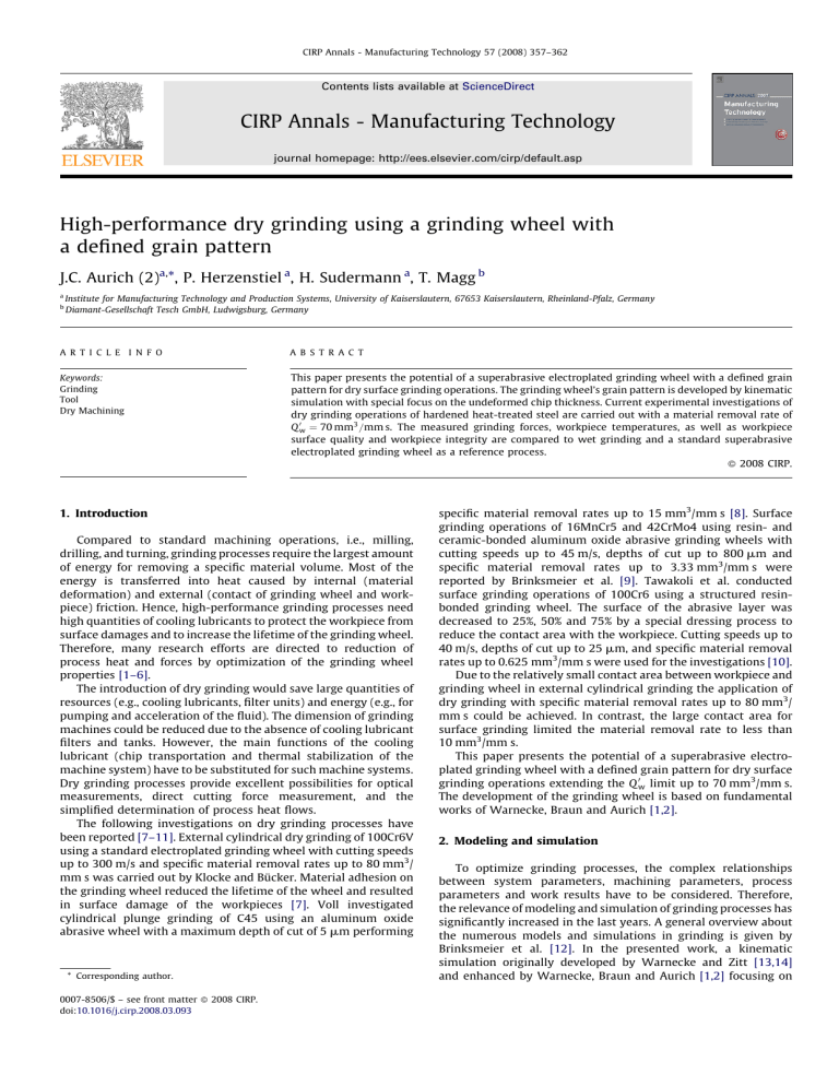
CIRP Annals - Manufacturing Technology 57 (2008) 357–362 Contents lists available at ScienceDirect CIRP Annals - Manufacturing Technology journal homepage: http://ees.elsevier.com/cirp/default.asp High-performance dry grinding using a grinding wheel with a defined grain pattern J.C. Aurich (2)a,*, P. Herzenstiel a, H. Sudermann a, T. Magg b a b Institute for Manufacturing Technology and Production Systems, University of Kaiserslautern, 67653 Kaiserslautern, Rheinland-Pfalz, Germany Diamant-Gesellschaft Tesch GmbH, Ludwigsburg, Germany A R T I C L E I N F O A B S T R A C T Keywords: Grinding Tool Dry Machining This paper presents the potential of a superabrasive electroplated grinding wheel with a defined grain pattern for dry surface grinding operations. The grinding wheel’s grain pattern is developed by kinematic simulation with special focus on the undeformed chip thickness. Current experimental investigations of dry grinding operations of hardened heat-treated steel are carried out with a material removal rate of Q 0w ¼ 70 mm3 =mm s. The measured grinding forces, workpiece temperatures, as well as workpiece surface quality and workpiece integrity are compared to wet grinding and a standard superabrasive electroplated grinding wheel as a reference process. ß 2008 CIRP. 1. Introduction Compared to standard machining operations, i.e., milling, drilling, and turning, grinding processes require the largest amount of energy for removing a specific material volume. Most of the energy is transferred into heat caused by internal (material deformation) and external (contact of grinding wheel and workpiece) friction. Hence, high-performance grinding processes need high quantities of cooling lubricants to protect the workpiece from surface damages and to increase the lifetime of the grinding wheel. Therefore, many research efforts are directed to reduction of process heat and forces by optimization of the grinding wheel properties [1–6]. The introduction of dry grinding would save large quantities of resources (e.g., cooling lubricants, filter units) and energy (e.g., for pumping and acceleration of the fluid). The dimension of grinding machines could be reduced due to the absence of cooling lubricant filters and tanks. However, the main functions of the cooling lubricant (chip transportation and thermal stabilization of the machine system) have to be substituted for such machine systems. Dry grinding processes provide excellent possibilities for optical measurements, direct cutting force measurement, and the simplified determination of process heat flows. The following investigations on dry grinding processes have been reported [7–11]. External cylindrical dry grinding of 100Cr6V using a standard electroplated grinding wheel with cutting speeds up to 300 m/s and specific material removal rates up to 80 mm3/ mm s was carried out by Klocke and Bücker. Material adhesion on the grinding wheel reduced the lifetime of the wheel and resulted in surface damage of the workpieces [7]. Voll investigated cylindrical plunge grinding of C45 using an aluminum oxide abrasive wheel with a maximum depth of cut of 5 mm performing * Corresponding author. 0007-8506/$ – see front matter ß 2008 CIRP. doi:10.1016/j.cirp.2008.03.093 specific material removal rates up to 15 mm3/mm s [8]. Surface grinding operations of 16MnCr5 and 42CrMo4 using resin- and ceramic-bonded aluminum oxide abrasive grinding wheels with cutting speeds up to 45 m/s, depths of cut up to 800 mm and specific material removal rates up to 3.33 mm3/mm s were reported by Brinksmeier et al. [9]. Tawakoli et al. conducted surface grinding operations of 100Cr6 using a structured resinbonded grinding wheel. The surface of the abrasive layer was decreased to 25%, 50% and 75% by a special dressing process to reduce the contact area with the workpiece. Cutting speeds up to 40 m/s, depths of cut up to 25 mm, and specific material removal rates up to 0.625 mm3/mm s were used for the investigations [10]. Due to the relatively small contact area between workpiece and grinding wheel in external cylindrical grinding the application of dry grinding with specific material removal rates up to 80 mm3/ mm s could be achieved. In contrast, the large contact area for surface grinding limited the material removal rate to less than 10 mm3/mm s. This paper presents the potential of a superabrasive electroplated grinding wheel with a defined grain pattern for dry surface grinding operations extending the Q 0w limit up to 70 mm3/mm s. The development of the grinding wheel is based on fundamental works of Warnecke, Braun and Aurich [1,2]. 2. Modeling and simulation To optimize grinding processes, the complex relationships between system parameters, machining parameters, process parameters and work results have to be considered. Therefore, the relevance of modeling and simulation of grinding processes has significantly increased in the last years. A general overview about the numerous models and simulations in grinding is given by Brinksmeier et al. [12]. In the presented work, a kinematic simulation originally developed by Warnecke and Zitt [13,14] and enhanced by Warnecke, Braun and Aurich [1,2] focusing on 358 J.C. Aurich et al. / CIRP Annals - Manufacturing Technology 57 (2008) 357–362 Fig. 1. Grain geometry and distribution. Fig. 3. Simulation results of numerical dressing. grinding wheels with a defined grain pattern was applied and further developed. Fig. 1 shows the grain geometry and distribution for the computed model of the grinding wheel. The modeled grain size is similar to FEPA standard B301. Based on microscopic analysis of blocky grains used for manufacturing the grinding wheel with a defined grain pattern, a ratio of 1.13 of the long- and short-grain axis and a ratio of 3:1 of cubic and tetrahedral basic grain geometry was modeled. To generate more realistic grain shapes, planes with randomized orientation are cut off the grain’s basic geometries [14]. The design and the notation of the grain pattern are depicted in Fig. 2. Based on the applied manufacturing process, a grain protrusion height of 35% of the grain size is taken for modeling the grinding wheel. For an average short grain axis length of 305 mm and a standard deviation of 30 mm the average grain protrusion height is 107 mm. Within the simulation, grinding wheel wear is not considered. Hence, the workpiece material is removed by grains with high grain protrusion even if the chip thickness is more than 10 mm or 15 mm. However, for real grinding processes grains with very high chip thickness wear out very rapidly. The number of kinematic grains is increasing and the material removal process respectively the grinding forces are distributed to many grains until a stationary grinding process is reached. To simulate the stationary grinding process, a numerical dressing process of the modeled grinding wheel was performed. In detail, the grain protrusion height of every single grain is ideally cut down to a specified limit. Fig. 3 shows the impact of different dressing heights upon the percentage of kinematic grains out of the total number of grains during a stationary grinding process with constant setup parameters compared to the undressed grinding wheel. These results are used for the dressing process of the manufactured prototype and enable grinding with many kinematic grains starting from the first workpiece. Hence, a more uniform stress on the single grains can be achieved resulting in a steady state grinding process and a reduction of grain breakouts. In general, grain breakouts increase the stress to following grains. Hereby, the lifetime of a grinding wheel with a reduced number of grains is much more affected than of a standard electroplated Fig. 2. Notation of modeled grain patterns [2]. Fig. 4. Modeled grain pattern and simulation results. grinding wheel. To avoid a chain reaction of grain breakouts on a circumferential line on the grinding wheel with a defined grain pattern, as observed before by Braun et al. [2], the number of grains in each line was doubled. Fig. 4 shows the modeled grain pattern numerically dressed to a maximum grain protrusion height of 110 mm. In comparison to the Fig. 5. Reference wheel and prototype. J.C. Aurich et al. / CIRP Annals - Manufacturing Technology 57 (2008) 357–362 Table 1 Specification of grain pattern Grain Grain Grain Grain Grain size (DIN ISO 6106) line angle (a) line distance (Dx) distance (Dz) line displacement (Dzv) 359 4. Experiments Blocky B301 608 1500 mm 300 mm 100 mm real grinding wheel (Fig. 5) the dimensions of the modeled grinding wheel are 400 mm 5 mm instead of 400 mm 12 mm to save computing time. The simulated process is a stationary surface grinding process of one grinding wheel revolution with Q 0w ¼ 70 mm3 =mm s and depths of cut of 0.75 mm up to 5 mm. Concerning the simulation results, the specific number of momentarily active grains (N0mom ) and the mean value of the average chip thickness (hcu,med) of the kinematic grains during one simulated grinding wheel revolution are displayed. N0mom increases with increasing depth of cut of N0mom ¼ 19 mm1 for ae = 0.75 mm up to N 0mom ¼ 36 mm1 for ae = 5 mm. Due to the constant Q 0w the removed workpiece material volume within a time interval is constant and therefore independent of the depth of cut. Hence, the material removal process is distributed to more grains with increasing depth of cut which explains the decrease of the simulated average chip thickness. The average chip thickness falls from hcu,med = 0.156 mm for ae = 0.75 mm to hcu,med = 0.09 mm for ae = 5 mm. 3. Manufacturing and preparation of the prototype Based on the results of the simulation, the grain pattern for a prototype grinding wheel with the dimensions 400 mm 12 mm was specified (Table 1). To create the grain pattern, masking technologies were used for preliminary adhesion of the grains on the steel wheel hub. For completion, a standard electroplating process was applied. About 35,000 grains were placed to form the abrasive layer of the wheel (Fig. 5). Due to the prototypical manufacturing technology, up to five grain lines at three positions are missing on the wheel (less than 2% of the total number of grain lines). However, the grinding wheel could be used for the whole series of experiments without further loss of grain lines. By using masking technology for manufacturing the presented prototype significant tool cost reduction could be achieved in comparison to the initially developed prototype wheel by Warnecke, Braun and Aurich [1,2], where each single grain was positioned manually. However, the tool costs of the prototype are still considerably higher in comparison to the used reference tool. After mounting the grinding wheel to the machine spindle (radial runout less than 1.5 mm) a touch-dressing operation was carried out. A rotating diamond dresser of 120 mm in diameter was used at a dressing speed ratio of qd = 0.6. The axial feed rate was 10 mm/rev and the infeed increment 1 mm. The uniformity of the maximum grain protrusion height as a result of the dressing process was checked by a roughness measurement in the negative profile of the grinding wheel. The negative profile was prepared by a plunge cut grinding process into a steel sheet of 1 mm thickness. The average roughness height (Ra) and the 10-point height (Rz) of the steel sheet were measured. Before dressing the roughness was Ra = 10.59 mm and Rz = 52.29 mm and after dressing Ra = 0.44 mm and Rz = 3.73 mm. The average grain protrusion height of the grinding wheel was measured by analysis of 30 single grains of the grinding wheel’s surface replica using confocal microscopy. The replicas were prepared at specified positions on the grinding wheel. The average grain protrusion height was 118 mm before and 102 mm after dressing. According to the simulation results of Fig. 3, the number of kinematic grains increases to approximately 60% of the total number of grains due to the dressing process. Hence, the grinding forces are distributed uniformly to the grains and a stationary wear behavior of the grinding wheel can be assumed. The surface up grinding experiments were carried out on a high efficiency grinding machine with high stiffness. In addition to the grinding wheel with a defined grain pattern (prototype), a standard superabrasive electroplated grinding wheel of the same geometry and grain size was used as reference wheel (Fig. 5). As workpiece material heat-treated steel AISI 4140H (42CrMo4V, DIN EN 10132-3) of 60 2 HRC with the dimensions 125 mm 50 mm 10 mm was used. Cooling lubricant during wet grinding was grinding oil. The grinding process and its results were monitored by the following measurement techniques: grinding forces (normal and tangential direction) by dynamometer, effective spindle power by non-contact hall effect probe, workpiece temperature by thermocouple sensor, and surface roughness by tactile measurements. Within the experimental investigations three different setups with Q 0w ¼ 70 mm3 =mm s and varying depth of cut ae = 1, 2, 3 and 4 mm with constant cutting speed of vc = 100 m/s were performed (Table 2). 4.1. Grinding forces, spindle power and workpiece temperatures In Fig. 6a, the comparison of the net grinding forces and the net spindle power is depicted, i.e., impact of the cooling lubricant for wet grinding has been taken out. Therefore, in separate grinding passes of each parameter combination for wet grinding the feed motion during stationary grinding was stopped and grinding forces as well as spindle power caused by the cooling lubricant were recorded. For dry grinding the idling power was deducted. The displayed values of force and power are average values of at least three measurements during the stationary grinding process and are low-pass filtered (20 Hz). The maximum standard deviation of the normal forces is 25 N, tangential force 15 N and spindle power 0.5 kW. The workpiece temperatures during stationary grinding were measured by thermocouple sensors (diameter 0.5 mm) laterally fixed in 0.6 mm holes at a distance of 0.5 mm to the ground surface in the middle of the workpiece in the grinding direction (Fig. 6b). Distance variations of the thermocouple sensor and the ground surface were normalized by interpolating the distance–temperature curve of the corresponding workpiece. For wet grinding using the reference wheel and the prototype, an increase of grinding forces and power with increasing depth of cut can be observed in Fig. 6a. The prototype (Table 2, setup 2) shows lower grinding forces and spindle power in comparison to the reference wheel (Table 2, setup 1). Concerning the normal and tangential grinding forces, a reduction of 30–40% and 20–35%, respectively could be achieved. The reduction of spindle power was around 16–27%. For dry grinding the forces and the spindle power are nearly constant with a further reduction in comparison to wet grinding. Concerning workpiece temperatures (Fig. 6b) during dry grinding, a significant temperature increase from 530–1050 8C can be observed for increasing depth of cut. Wet grinding processes show nearly constant workpiece temperatures, apart from a minor deviation for ae = 2 mm. For wet grinding processes using the prototype wheel, lower workpiece temperatures in comparison to the reference wheel occur. The results for wet grinding consistently show a better process behavior for the prototype. Due to an increased ratio of material removing grains to ploughing grains for the prototype, the cutting Table 2 Setups of grinding experiments Setup Grinding wheel Lubricant use 1 Standard superabrasive grinding wheel (reference wheel) Defined grain pattern (prototype) Defined grain pattern (prototype) Yes 2 3 Yes No 360 J.C. Aurich et al. / CIRP Annals - Manufacturing Technology 57 (2008) 357–362 Fig. 7. Material adhesion on grinding wheel. due to lower feed rates were expected. Nevertheless, the workpiece temperatures remained nearly constant. This can be explained by higher heat removal by the cooling lubricant. The absence of cooling lubricant during dry grinding led to a higher heat flux into the workpiece and increased workpiece temperatures in comparison to wet grinding. While workpiece temperatures in wet grinding are constant for increasing depth of cut, the temperatures in dry grinding increase. The reason is an increased heat flux into the workpiece due to the increasing contact length combined with the decreasing feed rate. The higher heat flux heats a bigger volume of workpiece material and the grindability of the thermally softened material is increased. Therefore, grinding forces and spindle power in dry grinding do not increase. As a side effect of higher temperatures, adhesion of workpiece material on the prototype wheel occurred with high depths of cut (Fig. 7). Thus, the friction between grinding wheel and workpiece further increased and contributed to higher temperatures (Fig. 6b). However, the material adhesion did not damage the prototype and even after many grinding operations without active cleaning of the grinding wheel’s surface the material adhesion did not accumulate. Instead, a stationary self-cleaning process occurred. Existent material adhesion completely disappeared after grinding operations with low depth of cut of ae = 1 mm or 2 mm. After extensive experimental research a specific material removal of V 0w ¼ 80; 000 mm3 =mm was carried out with the prototype, including V 0w ¼ 45; 000 mm3 =mm of dry grinding operations. Concerning wheel wear only a few grain breakouts are detected by scanning electron microscopy (SEM) analysis. Primarily, abrasive wear of the grains occurred. 4.2. Workpiece surface quality The workpiece surface roughness was measured orthogonal to the grinding direction in the middle of the ground workpiece surface. Fig. 8 shows the mean value of three measurements of the 10-point height Rz. The maximum standard deviation is less than 1 mm. Fig. 6. Experimental results. (a) Grinding forces and spindle power and (b) workpiece temperatures. process is improved. Therefore, process forces and power are reduced. The reduced amount of ploughing grains results in a lower generation of heat and consequently lower workpiece temperatures. Furthermore, larger chip space enables a better chip transportation, a better lubrication of the contact zone, and therefore a higher heat removal rate. The increase of grinding forces and power with a larger depth of cut for wet grinding is based on increased contact lengths leading to more active grains and consequently increased friction. Initially, increased heat generation and higher heat flux into the workpiece Fig. 8. Workpiece surface roughness. J.C. Aurich et al. / CIRP Annals - Manufacturing Technology 57 (2008) 357–362 The growing surface roughness with increasing depth of cut for dry grinding and the nearly constant surface roughness for both wet grinding processes resemble a good correlation to the workpiece temperature in Fig. 6b. Due to higher workpiece temperatures and a softer workpiece material the cutting process at microscopic level is increasingly substituted by ploughing and is therefore less efficient. The best surface quality is achieved by the application of the reference wheel caused by higher amounts of grains with low chip thickness. The intensified material adhesion for higher temperatures in dry grinding contributes to rougher workpiece surfaces. Visual grinding burn did not occur either for wet or for dry grinding experiments using the prototype wheel. However, the surface of the dry grinding experiments compared to wet grinding was less shiny. Apparently, higher surface temperatures and the missing cooling lubricant enhanced the oxidation process on the surface. 4.3. Workpiece surface integrity For investigation of the workpiece surface integrities metallographic sections of the workpieces were prepared for microhardness and microstructure analysis. For the microstructure analysis the sections were etched for 20 s using 3% of alc. HNO3. The material of the workpiece AISI 4140H (42CrMo4V, DIN EN 10132-3) austenitizes at around 800 8C and tempers at around 550 8C. High cooling rates of austenitized material result in a hardness increase by martensitic hardening of the material. Tempering leads to a hardness decrease of the material. Hence, three different zones (Fig. 9) can occur on the metallographic sections dependant on the workpiece temperature and the cooling rate: rehardened zone, tempered zone and unmodified workpiece core. The different zones are identified by micro-hardness analysis (Fig. 9a) and their different microstructures verified by light microscope and SEM images. The transition of the rehardened zone to the tempered zone is identified by an abrupt hardness decrease to around 400 HV which allows for a very accurate measurement of the thickness of the rehardened zone. The transition of the tempered zone to the workpiece core cannot be identified clearly due to the continuous hardness increase towards the workpiece core. Therefore, a hardness state of 600 HV, which is almost the hardness of the workpiece core, is defined as transition to the core. In Fig. 9a, the micro-hardness of a workpiece with rehardened zone – exemplarily shown for dry grinding with ae = 2 mm – is depicted. The maximum measured micro-hardness of the rehardened layer is 800 HV. The hardness of the tempered zone starts around 380–400 HV, directly below the rehardened zone, and increases towards the workpiece core to 650 HV. For dry grinding operations, the rehardened and tempered zone show maximum thickness in comparison to the wet grinding processes (Fig. 9b). The rehardened and the tempered zone significantly increase from 400 mm to 1250 mm, respectively from 1000 mm to 6800 mm with increasing depth of cut. Although no cooling lubricant is used, fast cooling rates caused by a high heat flux into the workpiece and air cooling, enable martensitic hardening. For wet grinding using the prototype, the workpieces show no rehardened zones. The tempered zones increase from 1000 mm up to 1900 mm with increasing depth of cut. Wet grinding using the reference wheel results in rehardened zones of around 80 mm thickness for ae = 1 mm and 2 mm. For ae = 3 mm and 4 mm no rehardened zones occured. The tempered zone increases with higher depths of cut starting from 1000 mm up to 3000 mm. The thickness of the identified rehardened and tempered zones increases with higher heat flux into the workpiece as a consequence of higher workpiece temperatures. Hence, a good correlation to the measured workpiece temperatures occurred. Selected X-ray residual stress measurements on the workpiece surface (maximum penetration depth 5.5 mm) using Cr Ka radiation and sin2 C method for stress calculation are displayed Fig. 9. Microstructure and micro-hardness analysis. Fig. 10. Residual stresses on the workpiece surface. 361 362 J.C. Aurich et al. / CIRP Annals - Manufacturing Technology 57 (2008) 357–362 in Fig. 10. Residual stresses in grinding direction (sII) and normal to grinding direction (s?) were measured. The generated residual stresses reveal only compressive stresses at the workpiece surface. In grinding the residual stress state depends on the superposition of thermal and mechanical influences, accounting for tensile and compressive residual stresses, and material influences, e.g., phase transformations leading to tensile (volume decrease) or compressive stresses (volume increase) [11]. For dry grinding the occurring martensitic phase transformation (volume increase) within the rehardened zone and the mechanical influences overcompensate the thermal-induced tensile stresses and lead to compressive residual stresses. The same reasons are responsible for the occurrence of compressive stresses during wet grinding for ae = 1 mm using the reference wheel where a rehardened zone was also identified. For wet grinding using the prototype (ae = 1 mm and 4 mm) and the reference wheel (ae = 4 mm) instead of rehardened zones tempered zones occurred. Tempered zones are generated by martensitic to ferrite/perlite phase transformations causing a volume decrease and therefore accounting for tensile stresses. Since compressive residual stresses were measured on the workpiece surface the mechanical influences of the wheel– workpiece contact predominated the residual stress formation. 5. Conclusion and outlook Based on kinematic simulation, a prototype grinding wheel with a defined grain pattern was developed and high-performance dry surface grinding operations were carried out. To prove the capability of the prototype wheel, wet grinding operations of the prototype were compared to a standard electroplated superabrasive grinding wheel. The prototype showed better process behavior with lower grinding forces and power of up to 40% and lower workpiece temperatures in wet grinding. Grinding power, forces and workpiece temperatures as well as workpiece surface roughness, microstructure, micro-hardness and residual stresses were measured. The application of the prototype wheel for dry grinding led to higher workpiece temperatures and a higher alteration of surface layers in comparison to wet grinding. Higher workpiece temperatures improved the grindability of the material and decreased process forces and power. However, the workpiece quality of wet grinding process could not be reached. Finally, extensive experimental research of wet and dry surface grinding operations with Q 0w ¼ 70 mm3 =mm s and V 0w ¼ 80; 000 mm3 =mm did not damage the prototype and showed only minor abrasive wear at the grinding wheel. Future investigations will include the measurement of residual stress depth profiles for a better understanding of the alteration of surface layer. Due to high thermal impacts during dry grinding part form errors, e.g., workpiece flatness, will be measured. Moreover, dry grinding of different materials, e.g., high-temperature alloys will follow. Acknowledgements This research and development project was partly funded by the German Federal Ministry of Education and Research (BMBF) within the Framework Concept ‘‘Research for Tomorrow’s Production’’ and managed by the Project Management Agency Forschungszentrum Karlsruhe, Production and Manufacturing Technologies Division (PTKA-PFT). References [1] Aurich JC, Braun O, Warnecke G (2003) Development of a Superabrasive Grinding Wheel With Defined Grain Structure Using Kinematic Simulation. Annals of the CIRP 52(1):275–280. [2] Braun O, Warnecke G, Aurich JC (2005) Simulation-based Development of a Superabrasive Grinding Wheel with Defined Grain Structure. Proceedings NAMRC North American Manufacturing Research Conference, vol. 33, 351– 358. [3] Pinto FW, Wegener K, Kuster F, Wunder S, Kiser M (2005) Model to Optimise the Grain Pattern of Grinding Discs with Controlled Positions of the Abrasives. Proceedings of the 8th CIRP International Workshop on Modeling of Machining Operations, Chemnitz, Germany, 349–359. [4] Tawakoli T (2001) Innovatives System zum Schleifen, Abrichten und Fräsen. IDR 35:48–54. [5] Abele E (2007) Mehrtechnologie orientierte rekonfigurierbare Werkzeugmaschine, Final report METEOR 2010, BMBF. [6] Chattopadhyay AK, Hintermann HE (1994) On Performance of Brazed SingleLayer CBN Wheel. Annals of the CIRP 43(1):275–280. [7] Klocke F, Bücker C (1996) Trockenschleifen-Grenzbetrachtung zur Kühlschmierstoffreduzierung. IDR 1(96):26–35. [8] Voll M (1999) Schleifprozesse mit Korundwerkzeugen für die Trockenbearbeitung auslegen, vol. 105 (31). Maschinenmarkt, Würzburg. pp. 24–27. [9] Brinksmeier E, Brockhoff T, Walter A (1997) Minimalmengenschmierung und Trockenbearbeitung beim Schleifen, vol. 52 (3). Härterei-Technische Mitteilungen-HTM. pp. 166–170. [10] Tawakoli T, Westkaemper E, Rabiey M (2006) Dry Grinding by Special Conditioning. Proceedings CIRP International Conference on High Performance Cutting, Vancouver, . [11] Brockhoff T (1999) Grind-Hardening: A Comprehensive Overview. Annals of the CIRP 48(1):255–260. [12] Brinksmeier E, Aurich JC, Govekar E, Heinzel C, Hoffmeister H-W, Peters J, Rentsch R, Stephenson DJ, Uhlmann E, Weinert K, Wittmann M (2006) Advances in Modeling and Simulation of Grinding Processes. Annals of the CIRP 55(2):667–696. [13] Warnecke G, Zitt U (1998) Kinematic Simulation for Analyzing and Predicting High-Performance Grinding Processes. Annals of the CIRP 47(1):265–270. [14] Zitt U-R (1999) Modellierung und Simulation von Hochleistungsschleifprozessen, Dissertation, University of Kaiserslautern.
