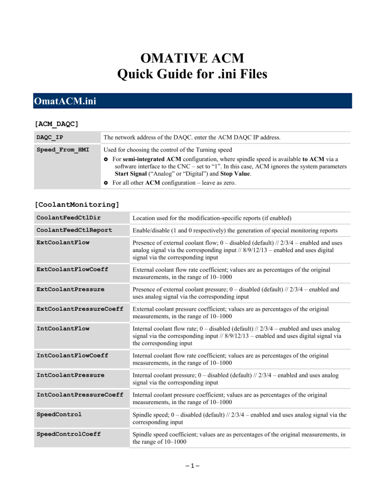
OMATIVE ACM Quick Guide for .ini Files OmatACM.ini [ACM_DAQC] DAQC_IP The network address of the DAQC. enter the ACM DAQC IP address. Speed_From_HMI Used for choosing the control of the Turning speed For semi-integrated ACM configuration, where spindle speed is available to ACM via a software interface to the CNC – set to “1”. In this case, ACM ignores the system parameters Start Signal (“Analog” or “Digital”) and Stop Value. For all other ACM configuration – leave as zero. [CoolantMonitoring] CoolantFeedCtlDir Location used for the modification-specific reports (if enabled) CoolantFeedCtlReport Enable/disable (1 and 0 respectively) the generation of special monitoring reports ExtCoolantFlow Presence of external coolant flow; 0 – disabled (default) // 2/3/4 – enabled and uses analog signal via the corresponding input // 8/9/12/13 – enabled and uses digital signal via the corresponding input ExtCoolantFlowCoeff External coolant flow rate coefficient; values are as percentages of the original measurements, in the range of 10–1000 ExtCoolantPressure Presence of external coolant pressure; 0 – disabled (default) // 2/3/4 – enabled and uses analog signal via the corresponding input ExtCoolantPressureCoeff External coolant pressure coefficient; values are as percentages of the original measurements, in the range of 10–1000 IntCoolantFlow Internal coolant flow rate; 0 – disabled (default) // 2/3/4 – enabled and uses analog signal via the corresponding input // 8/9/12/13 – enabled and uses digital signal via the corresponding input IntCoolantFlowCoeff Internal coolant flow rate coefficient; values are as percentages of the original measurements, in the range of 10–1000 IntCoolantPressure Internal coolant pressure; 0 – disabled (default) // 2/3/4 – enabled and uses analog signal via the corresponding input IntCoolantPressureCoeff Internal coolant pressure coefficient; values are as percentages of the original measurements, in the range of 10–1000 SpeedControl Spindle speed; 0 – disabled (default) // 2/3/4 – enabled and uses analog signal via the corresponding input SpeedControlCoeff Spindle speed coefficient; values are as percentages of the original measurements, in the range of 10–1000 –1– OMATIVE ACM Quick Guide for .ini Files FlowThresholdDefault Value representing a coolant flow rate in deciliters per minute. Range: integer from 0–300; default=100 PressureThresholdDefault Value representing a coolant pressure measured in bar. Range: integer from 0–100; default=10 [DNCKEY] AlarmFileNum The number of .mst files that will be saved in the …\ACM\Data\CrashReports folder. Acceptable range is 10-1000 files; the default value is 20. If the number of saved files exceeds the set value, old files are automatically deleted. AlarmLogging Used for turning the Alarm Logging function on or off 1 – activate logging of ACM information whenever ACM or CNC alarms are triggered (for CNC alarms, on semi-integrated ACM configuration only). This information includes current job name, current operation reference number, spindle power, feed rate override value, alarm number, etc. 0 – disable Logged information is saved in the file with the extension mst in the folder …\ACM\Data\CrashReports. The saved file has the name: yymmddHHMMSS_<mach_name>_<job_name>_ <tool_num>_R<ref_num>_<alarm_code>_ <chan_num>.mst Where: yymmddHHMMSS is a 12-digit number showing the time of the alarm <mach_name> is the name of the machine <job_name> is the name of the job <tool_num> is the current tool number or name <ref_num> is the operation reference number occurring at the time of the alarm Note: If the alarm was triggered while no ACM operation was running, the <ref_num> is missing from the file name. <alarm_code> is the alarm code triggered <chan_num> is the machine’s channel number AlarmRangeAfter Used with the Alarm Logging function. If AlarmLogging is set to “1”, this defines the amount of time (in seconds) after ACM/CNC alarm was triggered for which ACM information is saved. Acceptable range is 1 – 599 seconds; however, the sum of AlarmRangeBefore and AlarmRangeAfter cannot exceed 10 minutes (600 seconds). If the sum of these values is exceeded, the defaults are used. Default value is 120. AlarmRangeBefore Used with the Alarm Logging function. If AlarmLogging is set to “1”, this defines the amount of time (in seconds) before the ACM/CNC alarm was triggered for which ACM information is saved. Acceptable range is 1 – 599 seconds; however, the sum of AlarmRangeBefore and AlarmRangeAfter cannot exceed 10 minutes (600 seconds). If the sum of these values is exceeded, the defaults are used. Default value is 480. DNCKey Enter the ACM product key received from OMATIVE. –2– OMATIVE ACM DNCSpecific Quick Guide for .ini Files A number (created by formula) describing software options: For mill, turn, or mill-turn machine with main milling spindle: leave as zero. For ACM in Advanced Holemaking configuration on SINUMERIK machine: set to 1. For coolant flow and pressure monitoring with feed control on SINUMERIK machine: set to 15. For Spindle Speed Modulation/Spindle Speed Shifting for chatter suppression: set to 13. For turn-mill machine with main turning spindle: add 200 to the current value. For automatic job creation based on job operations: do not change the current value. For automatic job creation based on library operations: add 400 to the current value. Note: Depending on your specific configuration, more than one of the above attributes may be true. Add together all of the values that apply. IsExtendedLog Used for turning the Extended Logging function on or off. If software debugging is required, enter 1, otherwise leave empty. If 1 is entered, additional debugging information is written into the OmatACM.log file. Caution: Do not set parameter to 1 for a long time. LearningOnJobScope Used for saving learned load results. If your NC program is calling the same operation reference number (Ref. No.) more than once, this parameter lets you save the ACM learned results (Learned Load) for this Ref. No. as the highest maximum from all of the times this operation was called during this job. 0 (or nothing) – the maximum load is based only on the first use of the tool. 1 – the ACM learning result for this Ref. Num is the maximum of the learned results across the whole job (all uses). MinMillSpeed The minimum milling speed (in rpm) that will cause an alarm if alarm conditions occur. SerialNumber The MAC address of ACM DAQC (with the prefix “DAQC”) WaitOnStart Delay (in seconds) after CNC is booted before the ACM application will start In semi- and fully-integrated configurations where ACM starts automatically when the system powers on, ACM may be ready to establish communication channels before the system is ready. To avoid such problems, this parameter (measured in seconds) is used to delay ACM from establishing communication connections. This value is set separately for ACM and VCM. [ENV] CNC_IP The IP address of the CNC For stand-alone and fully integrated (Sinumerik 840D) ACM configurations: leave blank Otherwise: enter the CNC IP address CNC_Port The application port address on the CNC For semi-integrated ACM configurations enter the port number the ACM uses for communication with CNC. For all other ACM configuration: leave blank –3– OMATIVE ACM Quick Guide for .ini Files DefaultLanguage Defines the user interface language Default is English, “eng” For French – change to “fra” For German – change to “deu” For Italian – change to “ita” For Russian – change to “rus” For Spanish – change to “esp” HAddress The memory address on the CNC that is used for ACM For stand-alone and fully integrated (Sinumerik 840D) ACM configurations: leave blank Otherwise: enter the number of the macro variable of the CNC that will be used in ACM for operation referencing (for details see the “Setting up the NC Program” section in the OMATIVE ACM – User Manual) [HASP] MaxSpindles Maximum number of spindles; (only applies for ProductType of “0” or “4”) range = 1–4, default = 1 ProductType 0 – Mill (default) 1 – Turn 2 – Mill-Turn / Turn-Mill 3 – Multi-channel 4 – Mill (monitoring only) 5 – Turn (monitoring only) 6 – Mill-Turn / Turn-Mill (monitoring only) [MCODE] MaxMillRef The number of reference numbers reserved for milling operations (only on mill-turn or turn-mill machine for stand-alone ACM or for semi-integrated ACM, where operation referencing by some reasons is made via ACM DAQC): Enter the number of reference numbers reserved for milling operations among the total number of available reference numbers Otherwise: leave as zero [PART] Counter An auto-counting of the parts; may be used if the PartID is not defined. EndMode Used for setting how the part counting session is ended: 1 – automatically, with the “M30” in the NC program (does not require changes to program) 2 – by the OMATIVE “998” (“End-ACM”) marker OrderID [filled in from the ‘Main’ screen ‘Settings’ dialog] The factory order that this is a part of. The information needs to be filled in before the part has finished being cut. PartCounting Used for turning on (1) or off (0) the Exact Part Count feature –4– OMATIVE ACM Quick Guide for .ini Files PartID [filled in from the ‘Main’ screen ‘Settings’ dialog] The part ID for the part being made. The information needs to be filled in before the part has finished being cut. Program [filled in automatically] The name of the NC program being tracked in this part counting session. If an intermediate NC program is run (for example, to test the accuracy of the part cutting), the ending of that other program will not be recognized as the ending of this part. StartMode Used for setting how the part counting session is begun: 1 – automatically, with the start of the NC program (does not require changes to program) 2 – by the OMATIVE “997” (“Start-ACM”) marker State [filled in automatically] The current state of the Exact Part Count feature: 0 – not in process 1 – in process Note: This is shown as the Status on the ‘Main’ screen ‘Settings’ dialog and the ‘Status Monitoring’ screen ‘Settings’ dialog. For details, see the “Exact Part Count Reporting” section in the OMATIVE ACM – User Manual. [STANDREASON] SRAutoSetPeriod If not zero, the number of additional minutes after the SRPromptPeriod before the default “Stand Reason” is automatically applied. SRControlMode Defines whether or not the ACM system will switch out of “Standing” mode if a job is started (1=automatic, 0=manual). If logged in with access level 4, this can be controlled by on-screen buttons. Can be used by maintenance personnel if troubleshooting the system, but want ACM to continue in “Standing” mode. SRDefaultAutoCode The code number of the stand reason that will be automatically logged at the end of system at the end of the SRAutoSetPeriod. SRFileName If not blank, the name of the custom Stand Reasons file SRPromptPeriod If not zero, the number of minutes before the ACM system will start flashing a “Stand Reason” warning message. –5– OMATIVE ACM Quick Guide for .ini Files OmatMain.ini [MAIN] ACMPort Defines the port number used by the ACM application for communication with the OMATIVE-Pro application. Each OMATIVE application installed on the CNC/PC must have a unique port number. The default port number is 701. AlwaysOnTop Enables/disables ACM screen visibility on the monitor 0 – not always on top 1 – always on top (in front) of other applications KeyboardEnabled Enables/disables usage of virtual keyboard: 0 – virtual keyboard is not used 1– virtual keyboard is used MachineName The machine name that will appear on the ACM ‘Main’ screen MenuType Enables/disables vertical soft keys in ACM screens: 0 – no vertical soft keys 1 – vertical soft keys exist QssExt Used for defining the screen’s look When ACM is installed, a pair of generic (Gnr) files are included, defining the appearance of the application screen. These two files (applicationGnr.qss, omatstylesheetGnr_1024.qss) reside in the ~~~\ACM_m\appl directory. Note: The number at the end of the file name of the style-sheet file may be different, depending on what screen resolution the file was created for. If you also have both of these files but with a different extension (for example, “Fnc” for FANUC), then the QssExt value may be changed to this other extension to create a different look. Type ACM UseCloseDialog On the ACM ‘Main’ screen, controls what happens when the “Back” button ( ^ ) is pressed 0 – (default) the ACM application continues running, but the screen is hidden 1 – a confirmation dialog appears in order to close the ACM application [RESOLUTION] <various> If not blank, used for setting application window size and location If the width and height are not set, the ACM application selects a resolution from those supported, based on the desktop resolution. The OMATIVE supported list is: 640 x 480 1024 x 656 800 x 480 1024 x 768 800 x 600 1280 x 1024 If none of them match the desktop resolution, resolution is set to 1024x768. –6– 1280 x 768
