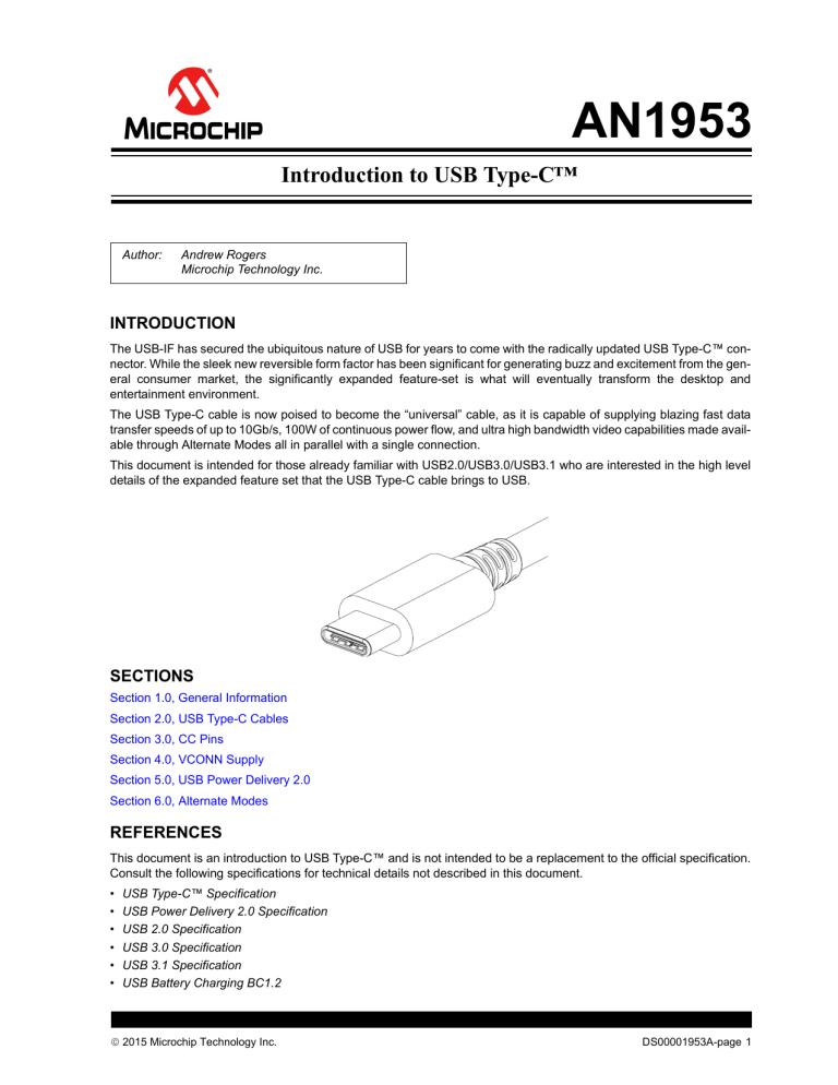
AN1953 Introduction to USB Type-C™ Author: Andrew Rogers Microchip Technology Inc. INTRODUCTION The USB-IF has secured the ubiquitous nature of USB for years to come with the radically updated USB Type-C™ connector. While the sleek new reversible form factor has been significant for generating buzz and excitement from the general consumer market, the significantly expanded feature-set is what will eventually transform the desktop and entertainment environment. The USB Type-C cable is now poised to become the “universal” cable, as it is capable of supplying blazing fast data transfer speeds of up to 10Gb/s, 100W of continuous power flow, and ultra high bandwidth video capabilities made available through Alternate Modes all in parallel with a single connection. This document is intended for those already familiar with USB2.0/USB3.0/USB3.1 who are interested in the high level details of the expanded feature set that the USB Type-C cable brings to USB. SECTIONS Section 1.0, General Information Section 2.0, USB Type-C Cables Section 3.0, CC Pins Section 4.0, VCONN Supply Section 5.0, USB Power Delivery 2.0 Section 6.0, Alternate Modes REFERENCES This document is an introduction to USB Type-C™ and is not intended to be a replacement to the official specification. Consult the following specifications for technical details not described in this document. • • • • • • USB Type-C™ Specification USB Power Delivery 2.0 Specification USB 2.0 Specification USB 3.0 Specification USB 3.1 Specification USB Battery Charging BC1.2 2015 Microchip Technology Inc. DS00001953A-page 1 AN1953 1.0 GENERAL INFORMATION The USB Type-C™ cable is a reversible 24-pin interconnect created by the USB-IF. The USB Type-C™ specification was first released in August 2014. The USB Type-C cable is a universal cable that addresses the needs for a wide range of computing, display, and charging applications. The long-term objective of the USB Type-C cable is to replace all previous iterations of the USB cable while greatly expanding the overall capabilities. The recent introduction of the USB Power Delivery and Alternate Mode capabilities further expand the raw potential for even greater adoption of the USB standard in a wider range of applications. USB CABLE PLUG FORM FACTORS 1 2 4 3 USB2.0 Type-B 6 7 8 9 4 3 2 1 USB3.0 Type-A 56789 54321 54321 USB2.0 Mini-A USB2.0 Mini-B 1 2 4 3 USB3.0 Type-B 12345 12345 USB2.0 Micro-A USB2.0 Micro-B 1.1 12345 A1 A2 A3 A4 A5 A6 A7 A8 A9 A10 A11 A12 4 3 2 1 USB2.0 Type-A 5 B1 B2 B3 B4 B5 B6 B7 B8 B9 B10 B11 B12 FIGURE 1: 6 7 8 9 10 USB3.0 Micro-B USB Type-C Port Behavior Prior to the introduction of USB Type-C™ and USB Power Delivery, data and power roles were typically fixed. The shape of the receptacle/plug dictated both its data role and power role. USB Type-C connections are much more flexible; ports may be host-mode only, device-mode only, or dual-role and both the data and power roles can be independently and dynamically swapped using USB Power Delivery protocol. Because of this, there is some new terminology that is used to describe USB Type-C systems. • Downstream Facing Port (DFP) - A host or downstream hub port. Typical of a legacy standard Type-A port. • Upstream Facing Port (UFP) - A device or upstream hub port. Typical of a legacy standard Type-B port. • Dual-Role Port (DRP) - A port that transitions between DFP and UFP port states until an attach event occurs. DRPs may be dynamically swapped using USB Power Delivery Protocol Negotiation after an initial attach event. • Power Source or Provider - A source of 5V-20V up to 5A. Typical of a legacy standard Type-A port. • Power Sink or Consumer - A sink of 5V-20V up to 5A. Typical of a legacy standard Type-B port. 1.2 1.2.1 Features MINIMUM FEATURE SET A basic USB Type-C application can still be cost-effective.USB Type-C ports are not required to implement all of the advanced features that are defined in the specification. The minimum required feature set includes the following: • USB2.0 Connection • Cable attach and detach detection • VCONN active cable supply DS00001953A-page 2 2015 Microchip Technology Inc. AN1953 1.2.2 BATTERY CHARGING While BC1.2 is still supported over USB Type-C because it depends on the USB2.0 lane, a significantly simplified and higher power current capability mechanism is also implemented. This simplified approach involves resistor pull-down/ pull-up relationships. These pull-down/pull-up resistors are connected to the CC wire and the upstream facing port (UFP) must monitor the voltage on the CC1 and CC2 pins in order to detect the current sourcing capability of the downstream facing port (DFP) it is connected to. This is a substantial improvement over the complicated handshake mechanisms involved with USB BC1.2. The basic USB Type-C current capabilities are Default USB (500mA for USB2.0 and 900mA for USB3.0), 1.5A@5V, and 3A@5V. For additional details see Section 3.0, CC Pins. 1.2.3 USB2.0, USB3.0, USB3.1, AND BEYOND The USB Type-C cable is designed to support current generation USB2.0 (480 Mb/s), USB3.0 (5Gb/s), USB3.1 (10Gb/ s), and future USB specifications reaching up to 20Gb/s data rates. For additional details see please refer to the individual specifications as published by the USB-IF. 1.2.4 POWER DELIVERY 2.0 USB Power Delivery protocol is a singled-ended, 1-wire protocol created by the USB-IF which specifies the methods for serial communication over the USB Type-C CC wire. USB Power Delivery is required for implementation of the following advanced features: • • • • • Communicating with an electronically marked/active cable Elevating the VBUS voltage above 5.5V Increasing current sourcing/sinking above 3A Changing default power roles (Provider or Consumer) Using Alternate Modes (see section 1.2.5) The Power Delivery 2.0 is a port-to-port and port-to-cable communication protocol. The communication can not propagate throughout an entire device tree like standard USB protocols. For additional details see Section 5.0, USB Power Delivery 2.0. 1.2.5 ALTERNATE MODES (THIRD PARTY PROTOCOLS) The USB Type-C cable allows for any third party protocol to be used as long as the cable can support it. Alternate Modes are negotiated and entered on a port-to-port basis using the USB Power Delivery protocol. The following signals may be reassigned when entering an Alternate Mode. • • • • • TX1+/RX1+/TX2+/RX2+/SBU1/SBU2 Separate specifications define the rules for each Alternate Mode. Currently, specifications exist for DisplayPort (authored by VESA) and ThunderBolt (authored by Intel). For additional details see Section 6.0, Alternate Modes. 1.3 Connector/Receptacle Pins FIGURE 2: USB TYPE-C RECEPTACLE A1 A6 A7 GND TX1+ TX1- VBUS CC1 D+ D- SBU1 VBUS RX2- RX2+ GND GND RX1+ RX1- VBUS SBU2 D- D+ CC2 VBUS TX2- TX2+ GND B7 B6 B12 A2 B11 2015 Microchip Technology Inc. A3 B10 A4 B9 A5 B8 A8 B5 A9 B4 A10 B3 A11 B2 A12 B1 DS00001953A-page 3 AN1953 FIGURE 3: USB TYPE-C PLUG A12 A11 A10 A9 A8 GND RX2+ RX2- VBUS SBU1 A7 A6 D- D+ GND TX2+ TX2- VBUS VCONN B1 B2 B3 B4 B5 A5 A4 A3 A2 A1 CC VBUS TX1- TX1+ GND SBU2 VBUS RX1- RX1+ GND B6 B7 B8 B9 B10 B11 B12 The USB Type-C connector has 24 pins. Because of its reversibility, the pins are arranged in a mirrored configuration. There are a total of 6 differential pairs in a full-featured cable assembly. There are also 4 pins that serve functions new to USB: CC1, CC2, SBU1, SBU2. 1.3.1 USB2.0 DIFFERENTIAL PAIRS The 2 sets of USB2.0 differential pairs in the connector pinout only connect to a single differential pair in standard USB2.0 or Full Featured USB Type-C cables. In a typical design, the D+ and D- pins are simply shorted on the PCB so that a multiplexer or switch is not required. The second set of pins (B6/B7) may only be re-purposed in docking type applications where only 1 orientation is possible. 1.3.2 USB3.1 DIFFERENTIAL PAIRS By default, only one set of TX/RX differential pairs are used for USB3.0/USB3.1 communication, depending on cable insertion orientation. Because of the cable reversibility, the USB3.0/USB3.1 lanes must be rerouted upon orientation connection. A typical application may use a 2:1 multiplexer to achieve this. USB Power Delivery protocol and Alternate Modes allow some or all of the TX/RX differential pairs to be reassigned. 1.3.3 CC1/CC2 PINS The CC1 and CC2 pins are used to connect to the either the CC or VCONN wire in a USB Type-C cable. Both CC1 and CC2 pins must be able to support both CC and VCONN functions. The function is detected upon cable insertion. The CC wire is used to cable orientation detection, USB Type-C current capability advertisement and detection, and USB2.0 BMC communication. See Section 3.0, CC Pins for additional details. The VCONN wire is used to power active or electronically marked cables. See Section 4.0, VCONN Supply for additional details. 1.3.4 SBU1/SBU2 The SBU wires are lower speed signal wires that is allocated for Alternate Mode use only. USB Power Delivery is required for Alternate Mode negotiation before these pins may be used for any purpose. TABLE 1: USB TYPE-C™ RECEPTACLE PINOUT Pin Name Function Note A1 GND Power Support for 60W minimum (combined with all VBUS pins) A2 TX1+ USB3.1 or Alternate Mode 10Gb/s differential pair with TX1- A3 TX1- USB3.1 or Alternate Mode 10Gb/s differential pair with TX1+ A4 VBUS Power Support for 60W minimum (combined with all VBUS pins) A5 CC1 CC or VCONN — A6 D+ USB2.0 — A7 D- USB2.0 — A8 SBU1 Alternate Mode Lower speed side band signal A9 VBUS Power Support for 60W minimum (combined with all VBUS pins) A10 RX2- USB3.1 or Alternate Mode 10Gb/s differential pair with RX2+ A11 RX2+ USB3.1 or Alternate Mode 10Gb/s differential pair with RX2- A12 GND Power Support for 60W minimum (combined with all VBUS pins) DS00001953A-page 4 2015 Microchip Technology Inc. AN1953 TABLE 1: USB TYPE-C™ RECEPTACLE PINOUT (CONTINUED) Pin Name Function Note B1 GND Power Support for 60W minimum (combined with all VBUS pins) B2 TX2+ USB3.1 or Alternate Mode 10Gb/s differential pair with TX2- B3 TX2- USB3.1 or Alternate Mode 10Gb/s differential pair with TX2+ B4 VBUS Power Support for 60W minimum (combined with all VBUS pins) B5 CC2 CC or VCONN — B6 D+ USB2.0 — B7 D- USB2.0 — B8 SBU2 Alternate Mode Lower speed side band signal B9 VBUS Power Support for 60W minimum B10 RX1- USB3.1 or Alternate Mode 10Gb/s differential pair with RX1+ B11 RX1+ USB3.1 or Alternate Mode 10Gb/s differential pair with RX1- B12 GND Power Support for 60W minimum 1.4 Power Supply Options The USB Type-C Interconnect introduces two new native charging options, but is also compatible with legacy charging options. USB Power Delivery is also supported but optional. TABLE 2: USB TYPE-C™ POWER SUPPLY OPTIONS Mode Nominal Voltage Maximum Current USB2.0 5V 500mA USB3.0/USB3.1 5V 900mA USB BC1.2 5V 1.5A USB Type-C Current @ 1.5A 5V 1.5A USB Type-C Current @ 2.0A 5V 3.0A USB Power Delivery Up to 20V Up to 5A 2015 Microchip Technology Inc. DS00001953A-page 5 AN1953 2.0 USB TYPE-C CABLES 2.1 Physical Specifications 2.1.1 SIZE The USB Type-C receptacle opening is 8.34mm x 2.56mm. For comparison, the Type-A receptacle opening is 12.50mm x 5.12mm while the USB3.0 micro-AB receptacle opening is 12.25mm x 1.85mm 2.1.2 DURABILITY The USB Type-C cable must minimally support 10,000 mating cycles. 2.1.3 WIRE GAUGE Signal wire gauge is not explicitly specified in the USB Type-C™ specifications, but wires must be appropriately sized for the length and capabilities of the cable such that: • • • • Signal integrity on the USB2.0 and USB3.0 wires is preserved ~50Ω impedance on the CC and SBU1/SBU2 wires Maximum IR drop of 250mV on GND return Maximum IR drop of 500mV on VBUS 2.1.4 CABLE LENGTH Cable lengths are not explicitly specified in the USB Type-C™ specifications. However, the electrical requirements create some practical limits. USB3.1 Type-C to Type-C cable assemblies are allocated -6 dB loss at 5GHz, effectively limiting cable lengths to 1 meter. USB3.0 Type-C to Type-C cable assembly are allocated -7 dB loss at 5GHz, effectively limiting cable lengths to 2 meters. TABLE 3: USB TYPE-C CABLE LENGTH SUMMARY USB Version Cable Length USB2.0 ≤ 4 meters Current Rating USB 3A Supported 5A USB3.0 ≤ 2 meters 3A ≤ 1 meter 3A Optional Required Supported 5A USB3.1 Electronically Marked Optional Required Supported Required 5A 2.2 USB2.0 A standard USB2.0 Type-C cable assembly is shown in Figure 4 and Table 4. DS00001953A-page 6 2015 Microchip Technology Inc. AN1953 FIGURE 4: USB2.0 TYPE-C PLUG PIN-OUT GND RX1+ RX1VBUS SBU2 DD+ CC2 VBUS RX1+ RX1GND PCB GND TX1+ TX1VBUS CC1 D+ DSBU1 VBUS TX1+ TX1GND GND VBUS VBUS CC D+ D- VCONN Receptacle TABLE 4: GND VBUS VBUS GND GND Cable Cable Plug USB TYPE-C™ USB2.0 CABLE ASSEMBLY WIRING USB Type-C Plug 1 Wire USB Type-C Plug 2 Signal Name Wire Number Signal Name Pin A1, B1, A12, B12 GND 1 GND_PWRrt1 [GND_PWRrt2]* A1, B1, A12, B12 GND A4, B4, A9, B9 VBUS 2 PWR_VBUS1 [PWR_VBUS2]* A4, B4, A9, B9 VBUS Pin Signal Name A5 CC 3 CC A5 CC B5 VCONN [18] [PWR_VCONN]* B5 VCONN A6 DP 4 UTP_Dp A6 DP A7 DM 5 UTP_Dm A7 DM Shell Shield Braid Shield Shell Shield * Optional wires 2.3 Full Featured A standard full-featured USB Type-C cable assembly is shown in Figure 5 and Table 5. FIGURE 5: USB TYPE-C RECEPTACLE AND CABLE PLUG PCB GND RX1+ RX1VBUS SBU2 DD+ CC2 VBUS RX1+ RX1GND GND TX1+ TX1VBUS CC1 D+ DSBU1 VBUS TX1+ TX1GND Receptacle 2015 Microchip Technology Inc. GND RX1+ RX1VBUS SBU2 VCONN VBUS RX1+ RX1GND GND TX1+ TX1VBUS CC D+ DSBU1 VBUS TX1+ TX1GND Cable Cable Plug DS00001953A-page 7 AN1953 TABLE 5: USB TYPE-C™ FULL FEATURED CABLE ASSEMBLY WIRING USB Type-C Plug 1 Pin Signal Name Wire USB Type-C Plug 2 Wire Number Signal Name Pin Signal Name A1, B1, A12, B12 GND 1[16]* GND_PWRrt1 [GND_PWRrt2]* A1, B1, A12, B12 GND A4, B4, A9, B9 VBUS 2[17]* PWR_VBUS1 [PWR_VBUS2]* A4, B4, A9, B9 VBUS A5 CC 3 CC A5 CC B5 VCONN 18 PWR_VCONN B5 VCONN A6 DP 4 UTP_Dp A6 DP A7 DM 5 UTP_Dm A7 DM A2 SSTX1+ 6 SDPp1 B11 SSRX1+ A3 SSTX1- 7 SDPn2 B10 SSRX1- B11 SSRX1+ 8 SDPp2 A2 SSTX1+ B10 SSRX1- 9 SDPn2 A3 SSTX1- B2 SSTX2+ 10 SDPp3 A11 SSRX2+ B3 SSTX2- 11 SDPn3 A10 SSRX2- A11 SSRX2+ 12 SDPp4 B2 SSTX2+ A10 SSRX2- 13 SDPn4 B3 SSTX2- A8 SBU1 14 SBU_A B8 SBU2 B8 SBU2 15 SBU_B A8 SBU1 Shell Shield Braid Shield Shell Shield * Optional wires 2.4 Passive Cables A passive USB Type-C cable does not have embedded powered electronics. All passive cables must minimally support USB2.0, and it can support USB Power Delivery up to 60W of power. 2.5 Powered Cable: Electronically Marked An electronically marked cable has embedded electronics that can communicate with the USB ports via USB Power Delivery 2.0 BMC protocol. An electronically marked cable may be powered from the VCONN supply or directly from VBUS and may draw up to 70mW of total power. Use-case Example 1: All USB3.1 compatible USB Type-C cables must be electronically marked. Use-case Example 2: A 100W Power Delivery cable. Any cable capable of exceeding 60W of power carrying capability must be electronically marked and communicate is capabilities to the DFP port. An electronically marked cable will behave identically to a standard passive cable if inserted into a receptacle that does not support USB Power Delivery 2.0. 2.6 Powered Cable: Managed Active Cable A managed active cable is an electronically marked cable that also has powered USB data reconditioning circuitry. A managed active cable may be powered from the VCONN supply or directly from VBUS and may draw up to 1.0W of total power. Use-case Example: An active cable that uses repeaters/re-conditioners to extend the maximum cable length. A managed active cable will behave identically to a standard active cable if inserted into a receptacle that does not support USB Power Delivery 2.0. It will still be able to power itself from VCONN or VBUS. DS00001953A-page 8 2015 Microchip Technology Inc. AN1953 2.7 USB Type-C to Legacy USB Cables The USB Type-C™ specification also defines the allowable USB Type-C to Legacy USB cable assemblies. The following full cable assemblies are supported: • • • • • • • USB Type-C to Type-A (USB2.0) USB Type-C to Type-A (USB3.0/3.1) USB Type-C to Type-B (USB2.0) USB Type-C to Type-B (USB3.0/3.1) USB Type-C to Mini-B (USB2.0) USB Type-C to Micro-B (USB2.0) USB Type-C to Micro-B (USB3.0/3.1) Only two USB Type-C to Legacy adapters are defined: • USB Type-C to Type-A receptacle adapter • USB Type-C to Micro-B (USB2.0) 2015 Microchip Technology Inc. DS00001953A-page 9 AN1953 3.0 CC PINS The CC1 and CC2 pins are critical for basic USB Type-C operation. Resistors are attached to the CC pins in various configurations depending on whether the application is a downstream facing port (DFP), upstream facing port (UFP), or an electronically marked/active cable: - Rp pull-up resistors on downstream facing ports (Section 3.1) - Rd pull-down resistors on upstream facing ports (Section 3.2) - Ra pull-down resistor on electronically marked/active cables (Section 3.3) The CC1 and CC2 pins must be constantly monitored by the port to perform the following functions: - Cable attach and removal detection (Section 3.4) - Cable orientation detection (Section 3.5) - Basic USB Type-C current capability advertisement (Section 3.6) 3.1 DFP Rp Pull-Up Resistors The Rp pull-up resistors on a downstream facing port must be connected to both CC1 and CC2 pins, and may be pulled up to either 3.3V or 5.0V (a current source may also be used). The value of the resistor selected advertises the current supplying capability of the port to the device. The acceptable (per the USB Type-C™ specification) values for the Rp pull-up resistors and current sources are shown in the table below. TABLE 6: VALID DFP RP PULL-UP RESISTOR VALUES Resistor Pull-up to 4.75V - 5.5V Resistor Pull-up to 3.3V ± 5% Current Source to 1.7V - 5.5V Default USB Power (500mA for USB2.0, 900mA for USB3.0) 56 kΩ ± 20% 36 kΩ ± 20 80 µA ± 20% 1.5A @ 5V 22 kΩ ± 5% 12 kΩ ± 5% 180 µA ± 8% 3.0A @ 5V 10 kΩ ± 5% 4.7 kΩ ± 5% 330 µA ± 8% DFP Current Capability 3.2 UFP Rd Pull-Down Resistors. An upstream facing port must connect a valid Rp pull-down resistor to GND (or optionally, a voltage clamp) to both CC1 and CC2 pins. A 5.1kΩ ± 10% is the only acceptable resistor if USB Type-C charging of 1.5A@5V or 3.0A@5V is to be used. The details are shown in the table below. TABLE 7: 3.3 VALID UFP RD PULL-DOWN RESISTOR VALUES Rd Implementation Nominal Value Detect Power Capability? Current Source to 1.7V - 5.5V ± 20% voltage clamp 1.1V No 1.32V ± 20% resistor to GND 5.1kΩ No 2.18V ± 10% resistor to GND 5.1kΩ Yes 2.04V Active Cable Ra Pull-Down Resistors An active cable must connect an Ra resistor from the VCONN pin to GND. The Ra resistor may range from 800Ω to 1.2kΩ. 3.4 Cable Attach and Removal Detection A cable attach is detected when either of the CC1 or CC2 pins detects a valid Rp/Rd connection. For a standard USB connection, only one of the CC1/CC2 pins may detect a valid Rp/Rd connection, not both. DS00001953A-page 10 2015 Microchip Technology Inc. AN1953 5V to VBUS may only be applied when a valid cable attachment is detected. This prevents two downstream facing ports from back-driving current into each other. TABLE 8: CC1 CC2 State Position Open Open Nothing Connected* — Rd Open UFP Connected Unflipped Open Rd UFP Connected Flipped Open Ra Powered Cable/No UFP connected Unflipped Ra Open Powered Cable/No UFP connected Flipped Rd Ra Powered Cable/UFP connected Unflipped Ra Rd Powered Cable/UFP connected Flipped Rd Rd Debug Accessory Mode connected — Ra Ra Audio Adapter Mode connected — Note: 3.5 CONNECTION STATES (FROM DFP PERSPECTIVE) *DFP-to-DFP and UFP-to-UFP are undetectable states. Cable Orientation Detection The cable orientation is detected in the following way: - If the CC1 pin detects a valid Rp/Rd connection, then the cable is in the “Unflipped” orientation at that receptacle. - If the CC2 pin detects a valid Rp/Rd connection, then the cable is in the “Flipped” orientation at that receptacle. FIGURE 6: CABLE ORIENTATION DETECTION DFP UFP 5V USB Type-C Cable Rp Rp CC1 CC Wire CC2 “Unflipped” CC1 CC2 Rd Rd “Unflipped” DFP UFP 5V Rp USB Type-C Cable Rp CC1 CC2 CC Wire “Unflipped” CC1 CC2 Rd Rd “Flipped” 2015 Microchip Technology Inc. DS00001953A-page 11 AN1953 3.6 USB Type-C Current Advertisement Both the upstream facing port and the downstream facing port must monitor the voltage on the CC1 and CC2 pins to determine if a valid Rp/Rd or Rp/Ra connection has been made. The USB Type-C™ specification defines the following voltage ranges: TABLE 9: USB TYPE-C VOLTAGE RANGES Current Advertisement No Connection (Detached) Rp / Rd Connection Rp / Ra Connection 3A >2.75V 2.60V - 0.85V 0.80V - 0.00V 1.5A >1.65V 1.60V - 0.45V 0.40V - 0.00V Default USB (500mA/900mA) >1.65V 1.60V - 0.25V 0.20V - 0.00V Once a valid connection is established, the upstream facing port (device) may is responsible for drawing the appropriate amount of maximum current. DS00001953A-page 12 2015 Microchip Technology Inc. AN1953 4.0 VCONN SUPPLY VCONN is a 5V(4.75V - 5.5V allowable range) 1.0W power supply used to power circuits within the plug that are needed to implement electronically marked cables and VCONN-powered accessories. The DFP is responsible for supplying VCONN by default. If two Dual-Role ports with USB Power Delivery support are connected to each other, the VCONN supplier can be swapped via USB PD negotiation. VCONN is required for PD-enabled port and USB3 support. The VCONN power supply can be supplied in one of two ways: a) b) If a valid Rp/Rd connection is detected on one of the CC pins, the VCONN supply can be blindly routed to the opposite CC pin After a valid Rp/Rd connection is detected on one of the CC pins, the opposite CC pin can be monitored for a valid Rp/Ra connection before routing the VCONN supply to the pin. Because of the reversible nature of the USB Type-C cable, both CC1 and CC2 pins must be able to assume the role of CC and VCONN upon cable insertion. A typical solution is presented in fig xx below. FIGURE 7: DFP VCONN SUPPLY AND ACTIVE CABLE 5V Rp UFP VCONN USB Type-C Cable Rp CC1 CC2 VCONN Control CC2 Active Cable IC Ra Note: CC1 CC Wire Rd Ra Rd While all USB Type-C ports are required to source VCONN to active cables, active cables are permitted to source power from either VCONN or VBUS. 2015 Microchip Technology Inc. DS00001953A-page 13 AN1953 5.0 USB POWER DELIVERY 2.0 USB Power Delivery 2.0 refers to a single wire protocol (on CC wire) created by the USB-IF. The name “USB Power Delivery” can be somewhat misleading as it allows for much more than just power negotiations; it unlocks the advanced capabilities of the USB Type-C cable. The PD messaging occurs completely independently of USB2.0 or USB3.0/ USB3.1 data and is used for port-to-port negotiation of power roles, voltage level, maximum supplying current capability, data roles, and Alternate Modes. Port-to-powered cable communication is also handled by USB PD. 5.1 • • • • • • Protocol Details All communication occurs over CC wire. The DFP is the Bus Master and initiates all communication. All messages are 32-bit 4b/5b encoded Bi-phase mark coded (BMC). 300k Baud rate CRC32 error detection + message retries Terminology: - SOP: DFP to DFP messaging - SOP’: DFP to active cable plug messaging - SOP’’: DFP to active cable plug messaging FIGURE 8: SOP SIGNALING DFP UFP ELECTRONICALLY MARKED CABLE CABLE PLUG CABLE PLUG SOP’ SOP’’ SOP Note: 5.2 SOP’ is assigned to one plug of the cable while SOP’’ is assigned to the other. The cable plugs cannot tell which side that they are connected to, just that one end may respond to SOP’ addressed messages and the other may respond SOP’’ addressed messages. Power Delivery Negotiation USB Power Delivery allows power configuration of a USB connection to be dynamically modified. The default 5V voltage on VBUS can be reconfigured up to any level up to 20V. The maximum current supplying capability can also be raised to a maximum of 5A with a 100W compatible electronically marked USB PD Type-C cable. The default roles (Provider or Consumer) can also be dynamically swapped at any time if both ports support dual power role functionality and the port accepts the swap request. 5.3 Alternate Mode and Data Role Negotiation. Alternate Modes allow third party protocols to be transmitted over the USB Type-C cable. They are negotiated on portto-port basis with Power Delivery protocol. See Section 6.0, Alternate Modes for more information. Data roles can also be swapped dynamically over USB PD protocol negotiation. DS00001953A-page 14 2015 Microchip Technology Inc. AN1953 5.4 Billboard Device Because of the wide range of capabilities enabled with USB PD, it can become confusing for the end user. There may be times when a user connects two devices and expects a different result than what actually occurs. To provide some amount of feedback to the user, a USB2.0 “Billboard” class device connected to the Power Delivery system can provide messages to the user that can explain errors or compatibility issues. 2015 Microchip Technology Inc. DS00001953A-page 15 AN1953 6.0 ALTERNATE MODES Alternate Modes and USB Power Delivery are the two key features that will allow the USB Type-C cable to become a true “universal” cable. Alternate Modes allow the USB Type-C cable to be reconfigured to support third party protocols. This feature is enabled only if both ports support the USB Power Delivery protocol and are both compatible with the specific Alternate Mode. There are no specific limits on Alternate Modes. As long as the cable can support the third party protocol signaling while maintaining a USB2.0 connection, then the Alternate Mode can be implemented. The USB Type-C™ specification does not define any Alternate Modes; Each third party must maintain its own USB Type-C Alternate Mode specification. Alternate Mode negotiation is performed via USB Power Delivery protocol on a port-to-port basis. 6.1 Reconfigurable Pins All Alternate Modes must minimally maintain a USB2.0 and USB Power Delivery connection. The following pins/wires may be reconfigured for the use with the Alternate Mode. FIGURE 9: RECONFIGURABLE PINS ON A FULL FEATURED CABLE A12 A11 A10 A9 A8 GND RX2+ RX2- VBUS SBU1 A7 A6 D- D+ GND TX2+ TX2- VBUS VCONN B1 FIGURE 10: B2 B3 B4 B5 A4 A3 A2 A1 CC VBUS TX1- TX1+ GND SBU2 VBUS RX1- RX1+ GND B6 B7 B8 B9 B10 B11 B12 RECONFIGURABLE PINS ON A DIRECT CONNECT APPLICATION A12 A11 A10 A9 A8 GND RX2+ RX2- VBUS SBU1 A7 A6 D- D+ GND TX2+ TX2- VBUS VCONN B1 6.2 A5 B2 B3 B4 B5 A5 A4 A3 A2 A1 CC VBUS TX1- TX1+ GND SBU2 VBUS RX1- RX1+ GND B6 B7 B8 B9 B10 B11 B12 Example: DisplayPort DisplayPort was one of the first 3rd part protocols to be specified as a USB Type-C™ Alternate Mode. The DisplayPort Alternate mode supports the following modes of operation: • (2) Display Port lanes + (1) USB3.1 lane • (4) Display Port lanes FIGURE 11: (2) DISPLAY PORT LANES + (1) USB3.1 LANE EXAMPLE A12 A11 A10 A9 A8 GND DP1- DP0+ VBUS AUX+ A7 A6 D- D+ GND DP1+ DP0- VBUS VCONN B1 DS00001953A-page 16 B2 B3 B4 B5 A5 A4 A3 A2 A1 CC VBUS TX1- TX1+ GND AUX- VBUS RX1- RX1+ GND B6 B7 B8 B9 B10 B11 B12 2015 Microchip Technology Inc. AN1953 APPENDIX A: TABLE A-1: APPLICATION NOTE REVISION HISTORY REVISION HISTORY Revision Level & Date A (2-9-15) 2015 Microchip Technology Inc. Section/Figure/Entry Correction Unfinished Pre-Release DS00001953A-page 17 AN1953 THE MICROCHIP WEB SITE Microchip provides online support via our WWW site at www.microchip.com. This web site is used as a means to make files and information easily available to customers. Accessible by using your favorite Internet browser, the web site contains the following information: • Product Support – Data sheets and errata, application notes and sample programs, design resources, user’s guides and hardware support documents, latest software releases and archived software • General Technical Support – Frequently Asked Questions (FAQ), technical support requests, online discussion groups, Microchip consultant program member listing • Business of Microchip – Product selector and ordering guides, latest Microchip press releases, listing of seminars and events, listings of Microchip sales offices, distributors and factory representatives CUSTOMER CHANGE NOTIFICATION SERVICE Microchip’s customer notification service helps keep customers current on Microchip products. Subscribers will receive e-mail notification whenever there are changes, updates, revisions or errata related to a specified product family or development tool of interest. To register, access the Microchip web site at www.microchip.com. Under “Support”, click on “Customer Change Notification” and follow the registration instructions. CUSTOMER SUPPORT Users of Microchip products can receive assistance through several channels: • • • • Distributor or Representative Local Sales Office Field Application Engineer (FAE) Technical Support Customers should contact their distributor, representative or field application engineer (FAE) for support. Local sales offices are also available to help customers. A listing of sales offices and locations is included in the back of this document. Technical support is available through the web site at: http://microchip.com/support DS00001953A-page 18 2015 Microchip Technology Inc. AN1953 Note the following details of the code protection feature on Microchip devices: • Microchip products meet the specification contained in their particular Microchip Data Sheet. • Microchip believes that its family of products is one of the most secure families of its kind on the market today, when used in the intended manner and under normal conditions. • There are dishonest and possibly illegal methods used to breach the code protection feature. All of these methods, to our knowledge, require using the Microchip products in a manner outside the operating specifications contained in Microchip’s Data Sheets. Most likely, the person doing so is engaged in theft of intellectual property. • Microchip is willing to work with the customer who is concerned about the integrity of their code. • Neither Microchip nor any other semiconductor manufacturer can guarantee the security of their code. Code protection does not mean that we are guaranteeing the product as “unbreakable.” Code protection is constantly evolving. We at Microchip are committed to continuously improving the code protection features of our products. Attempts to break Microchip’s code protection feature may be a violation of the Digital Millennium Copyright Act. If such acts allow unauthorized access to your software or other copyrighted work, you may have a right to sue for relief under that Act. Information contained in this publication regarding device applications and the like is provided only for your convenience and may be superseded by updates. It is your responsibility to ensure that your application meets with your specifications. MICROCHIP MAKES NO REPRESENTATIONS OR WARRANTIES OF ANY KIND WHETHER EXPRESS OR IMPLIED, WRITTEN OR ORAL, STATUTORY OR OTHERWISE, RELATED TO THE INFORMATION, INCLUDING BUT NOT LIMITED TO ITS CONDITION, QUALITY, PERFORMANCE, MERCHANTABILITY OR FITNESS FOR PURPOSE. Microchip disclaims all liability arising from this information and its use. Use of Microchip devices in life support and/or safety applications is entirely at the buyer’s risk, and the buyer agrees to defend, indemnify and hold harmless Microchip from any and all damages, claims, suits, or expenses resulting from such use. No licenses are conveyed, implicitly or otherwise, under any Microchip intellectual property rights. Trademarks The Microchip name and logo, the Microchip logo, dsPIC, FlashFlex, KEELOQ, KEELOQ logo, MPLAB, PIC, PICmicro, PICSTART, PIC32 logo, rfPIC, SST, SST Logo, SuperFlash and UNI/O are registered trademarks of Microchip Technology Incorporated in the U.S.A. and other countries. FilterLab, Hampshire, HI-TECH C, Linear Active Thermistor, MTP, SEEVAL and The Embedded Control Solutions Company are registered trademarks of Microchip Technology Incorporated in the U.S.A. Silicon Storage Technology is a registered trademark of Microchip Technology Inc. in other countries. Analog-for-the-Digital Age, Application Maestro, BodyCom, chipKIT, chipKIT logo, CodeGuard, dsPICDEM, dsPICDEM.net, dsPICworks, dsSPEAK, ECAN, ECONOMONITOR, FanSense, HI-TIDE, In-Circuit Serial Programming, ICSP, Mindi, MiWi, MPASM, MPF, MPLAB Certified logo, MPLIB, MPLINK, mTouch, Omniscient Code Generation, PICC, PICC-18, PICDEM, PICDEM.net, PICkit, PICtail, REAL ICE, rfLAB, Select Mode, SQI, Serial Quad I/O, Total Endurance, TSHARC, UniWinDriver, WiperLock, ZENA and ZScale are trademarks of Microchip Technology Incorporated in the U.S.A. and other countries. SQTP is a service mark of Microchip Technology Incorporated in the U.S.A. GestIC and ULPP are registered trademarks of Microchip Technology Germany II GmbH & Co. KG, a subsidiary of Microchip Technology Inc., in other countries. A more complete list of registered trademarks and common law trademarks owned by Standard Microsystems Corporation (“SMSC”) is available at: www.smsc.com. The absence of a trademark (name, logo, etc.) from the list does not constitute a waiver of any intellectual property rights that SMSC has established in any of its trademarks. All other trademarks mentioned herein are property of their respective companies. © 2015, Microchip Technology Incorporated, Printed in the U.S.A., All Rights Reserved. ISBN: 978-1-63277-475-0 QUALITY MANAGEMENT SYSTEM CERTIFIED BY DNV == ISO/TS 16949 == 2015 Microchip Technology Inc. Microchip received ISO/TS-16949:2009 certification for its worldwide headquarters, design and wafer fabrication facilities in Chandler and Tempe, Arizona; Gresham, Oregon and design centers in California and India. The Company’s quality system processes and procedures are for its PIC® MCUs and dsPIC® DSCs, KEELOQ® code hopping devices, Serial EEPROMs, microperipherals, nonvolatile memory and analog products. In addition, Microchip’s quality system for the design and manufacture of development systems is ISO 9001:2000 certified. DS00001953A-page 19 Worldwide Sales and Service AMERICAS ASIA/PACIFIC ASIA/PACIFIC EUROPE Corporate Office 2355 West Chandler Blvd. Chandler, AZ 85224-6199 Tel: 480-792-7200 Fax: 480-792-7277 Technical Support: http://www.microchip.com/ support Web Address: www.microchip.com Asia Pacific Office Suites 3707-14, 37th Floor Tower 6, The Gateway Harbour City, Kowloon Hong Kong Tel: 852-2943-5100 Fax: 852-2401-3431 India - Bangalore Tel: 91-80-3090-4444 Fax: 91-80-3090-4123 Austria - Wels Tel: 43-7242-2244-39 Fax: 43-7242-2244-393 Denmark - Copenhagen Tel: 45-4450-2828 Fax: 45-4485-2829 Atlanta Duluth, GA Tel: 678-957-9614 Fax: 678-957-1455 Austin, TX Tel: 512-257-3370 Boston Westborough, MA Tel: 774-760-0087 Fax: 774-760-0088 Chicago Itasca, IL Tel: 630-285-0071 Fax: 630-285-0075 Cleveland Independence, OH Tel: 216-447-0464 Fax: 216-447-0643 Dallas Addison, TX Tel: 972-818-7423 Fax: 972-818-2924 Detroit Novi, MI Tel: 248-848-4000 Houston, TX Tel: 281-894-5983 Indianapolis Noblesville, IN Tel: 317-773-8323 Fax: 317-773-5453 Los Angeles Mission Viejo, CA Tel: 949-462-9523 Fax: 949-462-9608 New York, NY Tel: 631-435-6000 San Jose, CA Tel: 408-735-9110 Canada - Toronto Tel: 905-673-0699 Fax: 905-673-6509 DS00001953A-page 20 Australia - Sydney Tel: 61-2-9868-6733 Fax: 61-2-9868-6755 China - Beijing Tel: 86-10-8569-7000 Fax: 86-10-8528-2104 China - Chengdu Tel: 86-28-8665-5511 Fax: 86-28-8665-7889 China - Chongqing Tel: 86-23-8980-9588 Fax: 86-23-8980-9500 China - Hangzhou Tel: 86-571-8792-8115 Fax: 86-571-8792-8116 China - Hong Kong SAR Tel: 852-2943-5100 Fax: 852-2401-3431 China - Nanjing Tel: 86-25-8473-2460 Fax: 86-25-8473-2470 China - Qingdao Tel: 86-532-8502-7355 Fax: 86-532-8502-7205 China - Shanghai Tel: 86-21-5407-5533 Fax: 86-21-5407-5066 China - Shenyang Tel: 86-24-2334-2829 Fax: 86-24-2334-2393 China - Shenzhen Tel: 86-755-8864-2200 Fax: 86-755-8203-1760 China - Wuhan Tel: 86-27-5980-5300 Fax: 86-27-5980-5118 China - Xian Tel: 86-29-8833-7252 Fax: 86-29-8833-7256 India - New Delhi Tel: 91-11-4160-8631 Fax: 91-11-4160-8632 India - Pune Tel: 91-20-3019-1500 Japan - Osaka Tel: 81-6-6152-7160 Fax: 81-6-6152-9310 Japan - Tokyo Tel: 81-3-6880- 3770 Fax: 81-3-6880-3771 Korea - Daegu Tel: 82-53-744-4301 Fax: 82-53-744-4302 Korea - Seoul Tel: 82-2-554-7200 Fax: 82-2-558-5932 or 82-2-558-5934 France - Paris Tel: 33-1-69-53-63-20 Fax: 33-1-69-30-90-79 Germany - Dusseldorf Tel: 49-2129-3766400 Germany - Munich Tel: 49-89-627-144-0 Fax: 49-89-627-144-44 Germany - Pforzheim Tel: 49-7231-424750 Italy - Milan Tel: 39-0331-742611 Fax: 39-0331-466781 Italy - Venice Tel: 39-049-7625286 Malaysia - Kuala Lumpur Tel: 60-3-6201-9857 Fax: 60-3-6201-9859 Netherlands - Drunen Tel: 31-416-690399 Fax: 31-416-690340 Malaysia - Penang Tel: 60-4-227-8870 Fax: 60-4-227-4068 Poland - Warsaw Tel: 48-22-3325737 Philippines - Manila Tel: 63-2-634-9065 Fax: 63-2-634-9069 Singapore Tel: 65-6334-8870 Fax: 65-6334-8850 Taiwan - Hsin Chu Tel: 886-3-5778-366 Fax: 886-3-5770-955 Spain - Madrid Tel: 34-91-708-08-90 Fax: 34-91-708-08-91 Sweden - Stockholm Tel: 46-8-5090-4654 UK - Wokingham Tel: 44-118-921-5800 Fax: 44-118-921-5820 Taiwan - Kaohsiung Tel: 886-7-213-7830 Taiwan - Taipei Tel: 886-2-2508-8600 Fax: 886-2-2508-0102 Thailand - Bangkok Tel: 66-2-694-1351 Fax: 66-2-694-1350 China - Xiamen Tel: 86-592-2388138 Fax: 86-592-2388130 China - Zhuhai Tel: 86-756-3210040 Fax: 86-756-3210049 01/30/15 2015 Microchip Technology Inc.
