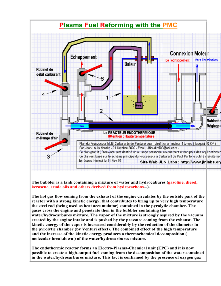
Plasma Fuel Reforming with the PMC The bubbler is a tank containing a mixture of water and hydrocabures (gasoline, diesel, kerosene, crude oils and others derived from hydrocarbons...). The hot gas flow coming from the exhaust of the engine circulates by the outside part of the reactor with a strong kinetic energy, that contributes to bring up to very high temperature the steel rod (being used as heat accumulator) contained in the pyrolytic chamber. The gases cross the engine and penetrate then in the bubbler containing the water/hydrocarbures mixture. The vapor of the mixture is strongly aspired by the vacuum created by the engine intake and is pushed by the pressure coming from the exhaust. The kinetic energy of the vapor is increased considerably by the reduction of the diameter in the pyrolytic chamber (by Venturi effect). The combined effect of the high temperature and the increase of the kinetic energy produces a thermochemical decomposition ( molecular breakdown ) of the water/hydrocarbures mixture. The endothermic reactor forms an Electro-Plasma-Chemical unit (EPC) and it is now possible to create a high-output fuel coming from the decomposition of the water contained in the water/hydrocarbures mixture. This fact is confirmed by the presence of oxygen gaz (O2) in great amount measured in the exhaust. Le bulleur est un réservoir contenant un mélange d'eau et d'hydrocarbures (essence, diesel, kérosène, huiles usagées et autres dérivés d'hydrocarbures... ). Le flux de gaz chauds provenant de l'échappement du moteur circule par la partie extérieur du réacteur avec une forte énergie cinétique , cela contribue à porter à très haute température la tige d'acier ( servant d'accumulateur de chaleur ) contenue dans la chambre à pyrolyse. Les gaz traversent le réacteur et pénètrent ensuite dans le bulleur contenant le mélange eau/carburant. Les vapeurs du mélange sont aspirées fortement par le vide créé par l'admission et poussées par la pression provenant de l'échappement. L'énergie cinétique des vapeurs est augmentée considérablement ( dans la partie bleu clair ) par la réduction du diamètre dans la chambre à pyrolyse ( effet de Venturi ). L'effet combiné de la haute température et de cette énergie cinétique accrue provoque la décomposition thermochimique du mélange eau/carburant. Le réacteur endothermique forme un ensemble électro-plasma-chimique (EPC) permettant de créer un carburant à haut rendement provenant de la décomposition de l'eau contenue dans le mélange eau/hydrocarbures est confirmée par la présence importante d'oxygène O2 dans les gaz d'échappement. Plasmatron (source : http://www.bellona.no/en/energy/report_31999/11197.html ) At the Massachusetts Institute of Technology (MIT), researchers are developing a reformer, which, like the KCB&H one, uses plasma for reforming hydrocarbons. The advantage of a plasma reformer is that it can use all forms of hydrocarbons, including heavy oil fractions. In addition, the plasma reforming can operate in pyrolytic mode (thermal degrading of organic material without air or oxygen) so that the carbon is turned into soot. This eliminates the formation of CO2. Plasma technology allows for a more compact and lighter design than traditional reformers because the reaction occurs much faster. MIT is studying use of the plasma reformer in the pyrolytic, partial oxidation and steam reforming methods mode. MIT's "Plasmatron" operates at temperatures of over 2,000 oC, and the amount of hydrogen produced is around 80-90%. The main disadvantage with plasma reforming is its dependency on electrical power. MIT hopes to lower the need for electricity to 5% of the fuel's combustibility caloric value through heat recycling and a better reactor design; today it is 20%. [L. Bromberg et al 1997/1998] Tests et plans d'une tondeuse équipée du PMC Full tests and diagrams of a lawnmower retrofited with the PMC Vidéos de démonstration de la tondeuse PMC en Haute Qualité High Quality videos about the PMC retrofited lawnmower Tests d'un groupe électrogène rétrofité avec le PMC by Philippe Driot Test of an electrical power generator retrofited with the PMCby Philippe Driot Détails complets et vidéos explicatives sur le PMC par M. David Full details and tutorial videos about the PMC by M. David Photos et vidéos de conseils sur les améliorations du PMC par M.David Tout sur le processeur multi-carburants de Paul Pantone par Quant'homme Des véhicules rétrofités avec succès... De nombreux conseils techniques pour les constructeurs du PMC par M.David Calcul de l'efficacité d'un rétrofit PMC sur la consommation d'un tracteur par C. Martz Le ChtiPantone, des tracteurs au PMC dans le Nord de la France "Avant son installation, le tracteur consommait 12-15 L/h. Lors du dernier essai contrôlé avec un broyeur de 3 mètres pendant 8 heures d'affilée, la consommation de gazole s'est stabilisée à 7.5 L/h pour une consommation d'eau de 1.7 L/h." SPAD Le SPAD(c) est un optimiseur compact de performances pour les moteurs diesel et essence, dérivé du PMC Pantone, proposé par APTE. La consommation de carburant et la pollution sont fortement réduites... Pour plus d'informations : http://easy.spad.free.fr/ The BingoFuel Reactor experiment The BingoFuel Reactor v1.0 ( 1080 liters/hour of fuel mixture ) Le BingoFuel Reactor v1.0 ( 1080 litres/heure de mélange de carburant ) Tests of the BingoFuel Reactor v1.1 Tests du BingoFuel Reactor v1.1 How to build the BingoFuel Reactor v1.1 Comment construire le BingoFuel Reactor v1.1 The CFR for producing BingoFuel... Produire du BingoFuel avec le CFR... The Worldwide BingoFuel Reactor BUILDERS LOGBOOK ( Updated 05-2903 ) Burning gas tests with the BingoFuel Reactor Tests de combustion du gaz produit par le BingoFuel Reactor A 5HP electrical generator fully powered with the BingoFuel Reactor Un groupe électrogène de 5 cv entièrement alimenté par le BingoFuel Reactor How to build a cheap and simple AquaFuel generator Patent : US 603,058 - Electrical Retort by Hilliary Eldridge April 26, 1898 Construction of a Simplified Wood Gas Generator for Fueling Internal Combustion Engines in a Petroleum emergency by The Biomass Energy Foundation Press See the full document at : http://www.gengas.nu/byggbes/index.shtml << This report is one in a series of emergency technology assessments sponsored by the Federal Emergency Management Agency (FEMA). The purpose of this report is to develeop detailed, illustrated instrucions for the fabrication, installation, and operation of a biomass gasifier unit (i.e. a "producer gas" generator, also called a "wood gas" generator) which is capable of providing emergency fuel for vehicles, such as tractors and trucks, should normal petroleum sources be severely disrupted for an extended period of time. These instructions have been prepared as a manual for use by any mechanic who is reasonably proficient in metal fabrication or engine repair. Fuel gas, produced by the reduction of coal and peat, was used for heating as early as 1840 in Europe and by 1884 had been adapted to fuel engines in England. Prior to 1940, gas generator units were a familiar, but not extensively utilized, technology. However, petroleum shortages during World War II led to widespread gas generator applications in the transportation industries of Western Europe. (Charcoal burning taxis, a related application, were still common in Korea as late as 1970.) The United States, never faced with such prolonged or severe oil shortages, has lagged far behind Europe and the Orient in familiarity with and application of this technology. However, a catastrophic event could disrupt the supply of petroleum in this country so severely that this technology might be critical in meeting the energy needs of some essential economic activities, such as the production and distribution of food. >> THE GAS PRODUCER - SCIENCE AND CONSTRUCTION The making of the Källe-gasifier by Torsten Källe The ALF Vaporizer system manual by Alan Francoeur ( with diagrams and photos ) The Brown's gas generator by Milan Manchich ( with diagrams and photos ) A working and tested water engine patented by François Cornish ( with diagrams and photos ) Copyright Information How to build yourself the BingoFuel Reactor v1.1 created on April 2, 2003 - JLN Labs - Last update April 22, 2003 Cliquez ici pour la version Française Toutes les informations et schémas sont publiés gratuitement ( freeware ) et sont destinés à un usage personnel et non commercial All informations and diagrams are published freely (freeware) and are intended for a private use and a non commercial use. You will find in this page all the details for building and testing yourself the BingoFuel Reactor v1.1. The BingoFuel Reactor v1.1 uses common parts which can be found easily in any plumbing shops, no machining and special tools are required. The main part used is a simple water filtration unit with its anti-scale cartdridge ( see the photo below ). Step 1 : remove the purge valve ( the red button ) from the head of the water filtration unit. Step 2 : put the 20x27 brass cap at the input and the 20x27 female-female adapter on the device at the output as shown in the pictures above Step 3 : drill a small hole into the 20x27 female cap and put a silicon tube with an adapter on the cap, and then screw the cap on the output of the head of the device Step 4 : Take the anti-scale cartridge and remove the bottom plastic grid and then all the crystals inside the cartdridge. Below, all the components required for building the plasma reaction chamber. Note : You must use two multiple thin wires cables ( 1.5 mm2 ) sheated with silicon due to the overheating of the wire produced by the strong current flow. You will find the required carbon rods in any rectangular 4.5 V Zinc-Carbon battery. Step 5 : Mount all the components as shown in the photo above Step 6 : Drill a 6 mm diameter hole at 25 mm from the bottom of the plastic cartridge, then fix the plasma igniters with a 6x25 mm nut and a bolt as shown in the photo above Step 7 : Place the reaction chamber into the transparent tank then fill the reactor with ordinary tap water Step 8 : Put modelling clay to close the hole around the electrical wires. Your BingoFuel Reactor is now ready for testing... Notes from Jean-Louis Naudin : The BingoFuel Reactor v1.1 is only a demonstrator, this is a proof of concept device which shows that the device works really. This version is able to produce a great amount of synthetic gas during some minutes. A new version of the BingoFuel Reactor is under development, this version ( v2.0 ) will be able to run for a long time without tuning and adjustment... Disclaimer : The author assumes no liability for any incidental, consequential or other liability from the use of this information. All risks and damages, incidental or otherwise, arising from the use or misuse of the information contained herein are entirely the responsibility of the user. Although careful precaution has been taken in the preparation of this material. Be Carefull, you must conduct this test in a well ventiled room or better in open air, you must not smoke during the test. This experiment is not intended for the inexperienced. User of this document should be very carefull to try anything out ! If you do it, the risk of any results is just yours. I take no responsibility of anything that might happen, let it be of a wrong information or anything else. See also : The BingoFuel Reactor The CFR for producing BingoFuel... The BingoFuel Reactor (*) uses ordinary tap water and low voltage electrical energy for producing a synthetic gas. A high temperature ( 3000-4000°C ) plasma is generated underwater by an electrical arc between carbon electrodes. The BingoFuel Reactor produces a mixture of carbon monoxide and hydrogen (COH2) and this gas can burn very cleanly in oxygen or air, and so it can be used as fuel for an internal combustion engine. When burned, COH2 produces carbon dioxide and water vapor, so it generates very little, if any, pollution to the environnement. << This gas burns cleanly, producing water vapor and only the amount of CO2 that was originally absorbed by the biological mass when it was growing in the ground. Contrast this with burning fossil fuels (oil and natural gas) which resurrect old buried carbon and add it to the atmosphere from ancient cemeteries in the ground. Instead, biomass gas burning recycles recently absorbed atmospheric carbon dioxide. The input energy is typically about a thousand watt-hours or about 3300 BTU to produce about 250 liters per hour of carbo-hydrogen (8.5 cubic feet per hour). With a heating value of over 500 BTU per cubic feet, the COH2 output energy exceeds 4000 BTU, often approaching 5000 BTU in high efficiency designs. Thus, this biomass gasification process has an overunity efficiency of about 125% to 150%. However, when the entire energetics of the system are accounted for, including the ultraviolet light radiation, heat loss, etc., estimates of 200% to 400% are reasonable. >> ( Document source : Future Energy Technologies by Thomas Valone ) Below, an analysis of this synthetic gas by the NASA (1) : Hydrogen 46.483 % Carbon Dioxide 9.329 Ethylene 0.049 Ethane 0.005 Acetylene 0.616 Oxygen 1.164 Nitrogen 3.818 Methane 0.181 Carbon 38.370 Monoxide Total 100.015 This device is fully based on the Hilliary Eldridge patent US 603,058 "Electrical Retort" granted on April 26, 1898. Today, there are a lot of names for this synthetic gas such as Aquafuel™, Aqualene™, Magnegas™, TrueFuel™, Carbo-hydrogen™.... The BingoFuel Reactor is filled with tap water and uses a low AC voltage ( about 30V ~ ) The BingoFuel Reactor converts tap water into a synthetic gas which can be used as fuel for an internal combustion engine.... Above, the ignition sequence of the BingoFuel Reactor v1.0 Animated video of the BFR v1.0 See the video of the BFR v1.0 in action To see the video, the free downloadable RealPlayer is required You may download free the RealPlayer 8 Basic at : http://proforma.real.com/real/player/blackjack.html Test RUN #1 Click on the picture above to see the video ( 613 Kb ) Test RUN #2 Click on the picture above to see the video ( 581 Kb ) Test RUN #3 Click on the picture above to see the video ( 634 Kb ) Click here to see an MPEG video of the BFR v1.0 in action ( 04-03-03 ) Gas OUTPUT Measurements : See the video of the Gas OUTPUT measurement Click on the picture above to see the video ( 1 Mb ) Volume of Synthetic Gas Volume of Fuel mixture Time 0.5 liter 3 liters 10 sec 3 liters 18 liters 1 minute 180 liters 1080 liters 1 hour Comments from JL Naudin : The Synthetic gas produced at the output by the BingoFuel Reactor is not able to burn itself, it must be mixed with air in proportion of 1/5 ( one volume of synthetic gas with five volumes of air ). So, the Fuel mixture useable for an internal combustion engine is 6 times more than the gas produced. The BingoFuel Reactor is able to produce about 1080 liters per hour of Fuel mixture.
