25 дрейфовое приближение. градиентный дрейф
реклама
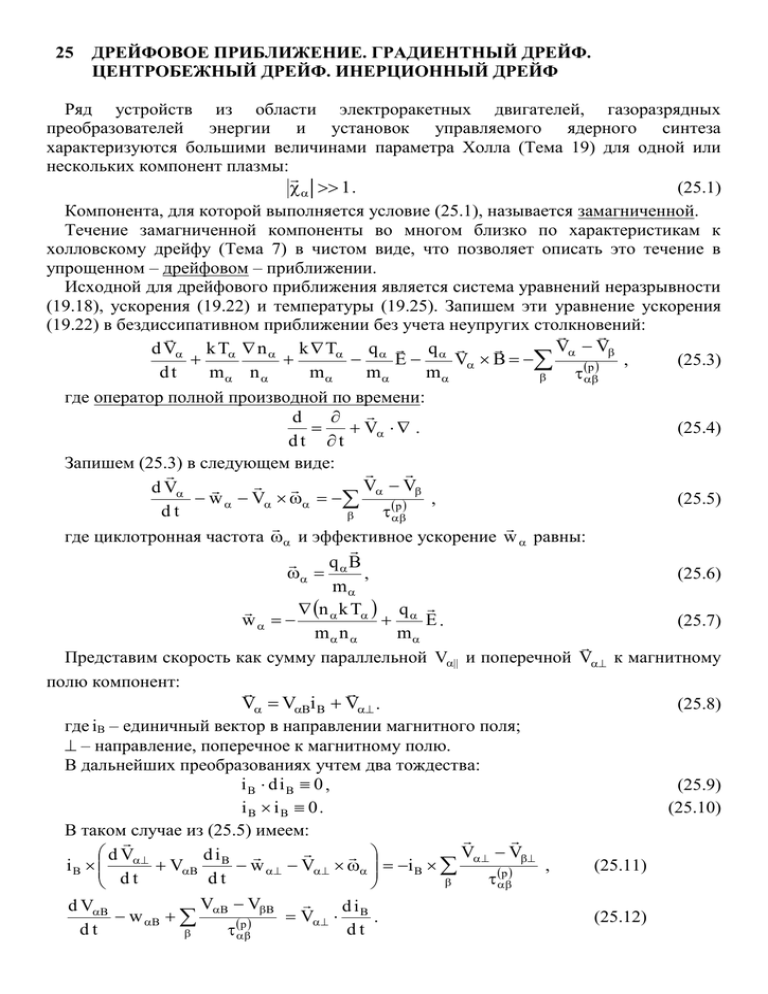
25 ДРЕЙФОВОЕ ПРИБЛИЖЕНИЕ. ГРАДИЕНТНЫЙ ДРЕЙФ. ЦЕНТРОБЕЖНЫЙ ДРЕЙФ. ИНЕРЦИОННЫЙ ДРЕЙФ Ряд устройств из области электроракетных двигателей, газоразрядных преобразователей энергии и установок управляемого ядерного синтеза характеризуются большими величинами параметра Холла (Тема 19) для одной или нескольких компонент плазмы: 1 . (25.1) Компонента, для которой выполняется условие (25.1), называется замагниченной. Течение замагниченной компоненты во многом близко по характеристикам к холловскому дрейфу (Тема 7) в чистом виде, что позволяет описать это течение в упрощенном – дрейфовом – приближении. Исходной для дрейфового приближения является система уравнений неразрывности (19.18), ускорения (19.22) и температуры (19.25). Запишем эти уравнение ускорения (19.22) в бездиссипативном приближении без учета неупругих столкновений: V V d V k T n k T q q E V B , (25.3) p dt m n m m m где оператор полной производной по времени: d V . (25.4) dt t Запишем (25.3) в следующем виде: V V d V w V , (25.5) p dt где циклотронная частота и эффективное ускорение w равны: qB , (25.6) m n k T q w E. (25.7) m n m Представим скорость как сумму параллельной V|| и поперечной V к магнитному полю компонент: V VBi B V . (25.8) где iB – единичный вектор в направлении магнитного поля; – направление, поперечное к магнитному полю. В дальнейших преобразованиях учтем два тождества: iB d iB 0 , (25.9) iB iB 0 . (25.10) В таком случае из (25.5) имеем: V V d V di i B VB B w V i B , (25.11) p d t d t VB VB d VB d iB w B V . (25.12) p dt dt С учетом того, что | | i B , имеем: i B V V , (25.13) В таком случае из (25.11): iB V V d V di i V w VB B B . (25.14) p dt d t В случае предельно большого магнитного поля, при из (25.14) следует: V 0 . (25.15) Это значит, что в сильном магнитном поле правая часть (25.12) и слагаемые левой части (25.15) являются малыми первого порядка сравнительно со слагаемыми левой части (25.12), а правая часть (25.15) – малой второго порядка. В первом приближении из (25.14) с учетом (25.4), (25.7) можно записать: q n k T i i V E V2Bi B i B VB B B . (25.16) m m n t Подстановка выражений для iB и в первое слагаемое (25.16) дает выражение для скорости холловского дрейфа (7.22): EB VH 2 . (25.17) B Из второго слагаемого (25.16) получаем выражение для так называемого градиентного дрейфа: B n k T grad n V grad . (25.18) q B2 Происхождение градиентного дрейфа можно продемонстрировать из Рис. 25.1. Пусть слева и справа от точки x мы имеем равные значения температур, т.е. равные значения скоростей частиц и при одинаковом значении индукции – циклотронных радиусов. Если при этом справа концентрация частиц больше, чем слева, то поток частиц, пришедших в точку x справа, будет превосходить встречный поток частиц, пришедших слева. Наоборот. Пусть слева и справа от точки x мы имеем равные значения концентраций. Если при этом справа температура (и скорости) частиц больше, чем слева, то поток частиц, пришедших в точку x справа, так же будет превосходить встречный поток частиц, пришедших слева. В обоих случаях мы имеем результирующий поток, поперечный одновременно к направленям магнитного поля и градиента давления частиц. Из третьего слагаемого (25.16) получаем выражение для так называемого центробежного дрейфа (Рис. 25.2): i B m V2B m V2B V i B i 2 . (25.19) x B qB qBR где i1, R – направление изменения и радиус кривизны линии магнитной индукции; i2 – направление, поперечное к магнитной индукции и направлению ее изменения. R iB x+rc x–rc B i 1 B i2 P Рис. 25.1 – Градиентный дрейф Рис. 25.2 – Центробежный дрейф Из четвертого слагаемого (25.16) получаем выражение для так называемого инерционного дрейфа: i B m VB m VB B i 2 . V i B (25.20) t qB q B t B где i1, R – направление изменения и радиус кривизны линии магнитной индукции; i2 – направление, поперечное к магнитной индукции и направлению ее изменения. 25 DRIFT APPROXIMATION. GRADIENT DRIFT. CENTRIFUGAL DRIFT. INERTIAL DRIFT The row of devices from area of electrojet engines, gas-discharge energy converters and installations of operated nucleus syntheses are characterized by great values of Hall parameter (the Subject 19) for one or several components of plasma: (25.1) 1 . The component, for which the condition (25.1) is fulfilled, is named magnetized. The current of magnetized component in much close to Hall driftage by characteristics (the Subject 7) per se, that allows to describe this current in simplified – drift – approximation. Basic for drift approximation is a system of equations of continuity (19.18), acceleration (19.22) and the temperature (19.25). Let’s write these equation of acceleration (19.22) in dissipativeless approximation disregarding non-elastic collisions: V V , d V k T n k T q q (25.3) E V B dt m n m m m p where the operator of the total derivative by the time: d V . dt (25.4) t Let’s write (25.3) in following form: V V d V w V p dt , where cyclotron frequency and efficient acceleration w are equal to: (25.5) qB , m n k T q . w E m n m (25.6) (25.7) Let’s represent velocity as the sum of parallel V|| and transverse V to magnetic field components: (25.8) V VBi B V . where iB – unit vector in direction of magnetic field; – direction, transverse to magnetic field. In further transformations there will be taken into account two identities: (25.9) iB d iB 0 , (25.10) iB iB 0 . In this case from (25.5) we have: V V , d V d iB (25.11) i V w V i B B dt dt d VB w B dt VB VB p B d iB V dt p . (25.12) With taking into account, that | | i B , we have: i B V V , (25.13) In this case from (25.11): d V d iB iB V w VB d t d t V V iB p . (25.14) In the case of extremely big magnetic field, under from (25.14) follows: (25.15) V 0 . This means, that in the powerfull magnetic field the right part (25.12) and the summands of the left part (25.15) are the little of the first order comparatively to the summands of the left part (25.12), and the right part (25.15) – the little of the second order. In the first approximation from (25.14) with taking into account (25.4), (25.7) may be written: q n k T iB iB . (25.16) V E V2Bi B i B VB m t mn The substitution of expressions for iB and in the first summand (25.16) gives the expression for velocity of Hall drift (7.22): EB. (25.17) VH B2 From the second summand (25.16) we get theexpression for so called gradient drift: B n k T . (25.18) grad n V grad q B2 The origin of gradient drift can be demonstrated from Fig. 25.1. Lets to the left and to the right from the point x we have equal values of the temperatures i.e. equal values of velocities of the particles and under the same value of induction – of cyclotron radiuses. If in this situation concentration of the particles to the right more, than to the left, then the flow of the particles, received in point x to the right, will exceed the counter flow of the particles, received to the left. On the contrary. Let’s to the left and to the right from the point x we have equal values of concentrations. If under this the temperature (and velocities) of the particles to the right more, than to the left, then the flow of the particles, received in point x to the right, will also exceed the counter flow of the particles, received to the left. In both cases we have the resulting flow, transverse simultaneously to directions of magnetic field and gradient of the pressure of the particles. From the third summand (25.16) get the expression for so called centrifugal drift (Fig. 25.2): i B m V2B m V2B V i B i 2 . x B qB qBR (25.19) where i1, R – direction of variation and radius of curvature of the line of magnetic induction; i2 – direction, transverse to magnetic induction and to direction of its variation. R iB x+rc x–rc B Fig. 25.1 – gradient drift B i 1 i2 P Fig. 25.2 – centrifugal drift From the fourth summand (25.16) we get the expression for so called inertial drift: i B m VB m VB B i 2 . V i B t qB q B t B (25.20) where i1, R – direction of variation and radius of curvature of the line of magnetic induction; i2 – direction, transverse to magnetic induction and to direction of its variation.
